I have been drawing out the schematic from the board. It's starting to make sense, the lights and buttons are memory mapped on the buss with 74HC273s and 244s/ The 273 flip-flops outputs are tied to the darlington arrays. One output drives one light. The 244 latches take the input from the switches. Switches are common to ground and pulls the input on the 244 low when pressed. Both the 273s and the 244s are on the bus all in parallel. The clock inputs for the 273s and the enable pins on the 244s are connected to a 74HC138 3 to 8 multiplexer. Outputs 0-2 to the 273s and 4 and 5 to the 244s. Inputs of the 138 are on bus lines A0-2.
Looking at this it seems there is no scanning routine like on a matrix keyboard and the lights are individually driven on the darlingtons so the Pokeys is looking more and more like a winner for this project. It would tie everything together and output a USB HID protocol and even handle the analog from the joystick.
http://www.poscope.com/pokeys56u
If anyone knows anything about this kind of code I can post it. Its a pretty short program.
No real use for this thing as of yet. Just too cool for it not to do something!
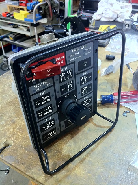
Weapon loader remote by macona, on Flickr
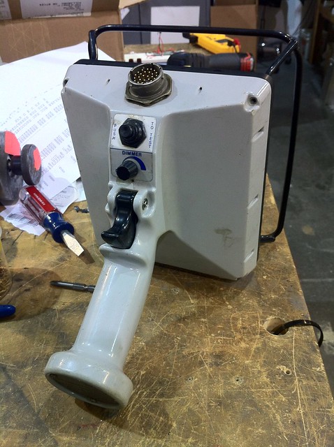
Weapon loader remote by macona, on Flickr
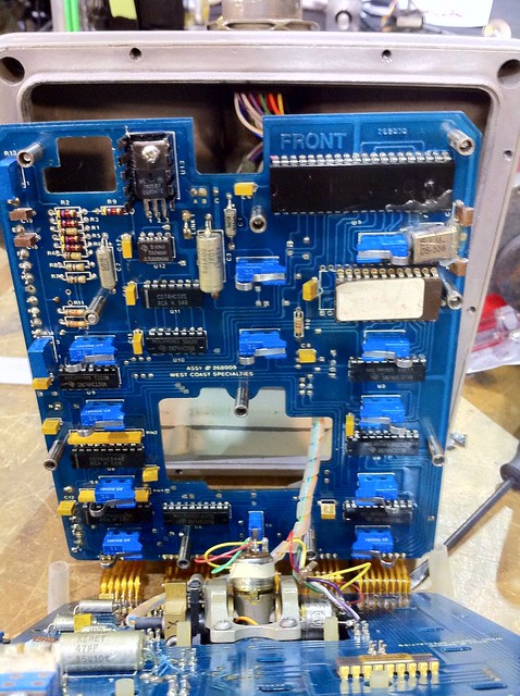
Weapon loader remote by macona, on Flickr
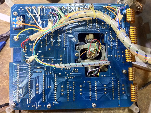
Weapon loader remote by macona, on Flickr