Well, I finally got a little transit time type data...but since a bunch of things have gone up in smoke, I think to make sense of it, I'm going to have to recalibrate the HV probe and a few other details. This measurement is HARD. Given the variety of things that could be going on in there, even the use of sine waves is a little suspect - am I off by a fraction of one, as shown, or is it a multiple of cycles + a fraction (which would make more sense with some of the numbers, these look too fast generally).
The picture looks like this:
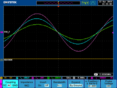
With no gas in there, and looking at the homebrew HV probe through another 100x probe, I managed to deskew the two faraday probes, and happily, the corrections needed were commensurate with the speed of light from the main grid (which was the driven element) and the distances to those faraday probes. So we're talking pico/nano second stuff - that's one great scope. (GDS-2204a GW Instek)

- deskewed with no gas present
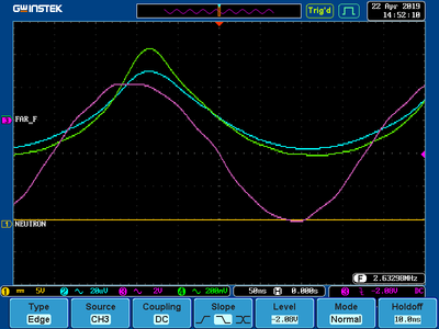
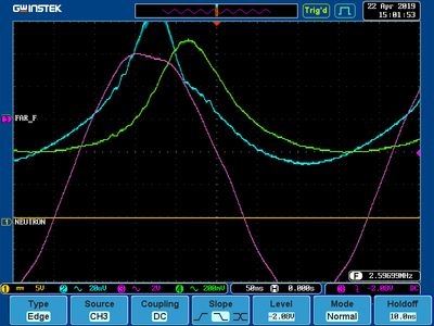
Purple is the main grid driven, the blue is the back (near) faraday probe, the green is the front/far one (main grid is at the back so I use back as the close probe)
Back probe is maybe 5" from the grid, front probe is another 10" or thereabouts. I haven't gone in there with a tape measure, and in fact I haven't opened the door in *years* and have kept it pumped down between runs to around e-6 mbar continuously. It's real clean in there...
Adding a lot of gas, say .06+ mbar indicated (about 3x what we really run with), I got this picture:

- Way more gas than usual
Going down to half that or so (there was some difficulty keeping things lit with just RF and I'm leaving a lot out here) I got this:

- Only double gas what we normally run with DC
I'm way not sure I'm able to give any sort of definitive interpretation here - a lot more data needs taken, things need re-calibrated (the ac response of that probe is sensitive somewhat to other things in the nearby, very intense, RF field for example, and I've had to replace one of the 3 divider boards since last calibration).
General observations are - if this thing gets lit with RF (to the point you can turn off the ion source) there is a diffuse glow all around the grid, and faint rays. The meter on the DC supply (otherwise turned off, but the meters work anyway) would be reading -1.x kv or so - there is self rectification in the tank as electrons hit the grid on positive peaks, which can also be seen in the clipping on the grid waveform in the pictures above. At this point the impedance goes WAY down and I can't get much RF on things, even with that new amp cranked (2kv on the plates at 200ma or so, and at resonance). I have not yet been able to keep this lit in this mode at the pressures we'd usually run.
I note that at lower gas pressure (longer mean free path) that the transit times (if that's what they are vs effectively dipole rotation propagation) are slower.
But still far faster than the voltages would calculate out reasonably, even for the lighter electrons. So I very strongly suspect that we're not seeing transit times here, but can't prove that - it's more like we have some sort of polarization of the plasma that is lots of little "which side of this ion is this electron on" stuff going on, and it takes awhile for one ion-electron pair to jiggle the one next to it, longer than it would take for an electron to go from the main grid to a faraday probe.
I see more bunching in the lower pressure - and it's kinda cool that there IS bunching, but this is hard to really prove unless I get some kind of exact gain matching on the probes, and as usual the scope goes 1,2,5 - and do please note that some of the scaling HAS BEEN CHANGED between scope screen shots.
For reference, assuming the two faraday probes are 10" difference in distance to the main, see the results of my little speed-volt calculator here for electrons and times:

- A little gui to calculate various speed/volt/mass ratio stuff. I think it's online here somewhere as speedvolt, if not, ask and I'll put it up. Perl_gtk3 program.
FWIW, there's another, completely different in behavior mode as well. We get the thing going with DC, at more or less our usual low pressures (1.9 e-2 mbar or so indicated), with say, 30kv DC @ < 5ma (just enough to get a really clean out of the noise neutron rate - a couple hundred k/second), and then add RF. In this mode, impedance stays high, and we get a lot more neutrons, more with more RF (I'm stuck at one frequency at a time due to needing resonant stuff in the RF supply), and the amount "more" is roughly consonant with the added peak voltage, which is interesting as half the time the RF is reducing the grid voltage....but it's early times and I need numbers I have more confidence in at this point. There are just an awful number of things that have to be done in order and checked at every step to ensure that I'm getting something worth believing in here. At lot of the automation I'd put together for DC only doesn't help much in this domain, so there may be some need to do a little work there too.
An issue with this "crazy load" as Bob said, is that running the RF amp near its limits is a little scary if you are suddenly changing the effective SWR dramatically. You have to keep an eye on how hot it's getting all the time, which takes time and mental effort away from getting good numbers elesewhere.