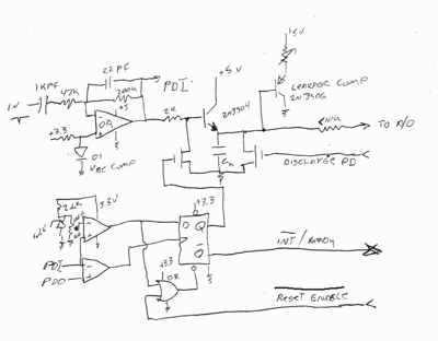
Been putting a little more thought into this, in particular after working with Phillipp's design. I think you really do need a way to prevent the peak detector from "re opening" when there is a signal present over threshold, so as not to catch the last part of some pulse and think you got the peak when all you got was the middle of the decay. On further study, some simplification seems possible, and some actual parts suggest themselves, so here goes. This could be done as a shield for arduino uno or chipkit uno32 (probably preferred, its A/D is far faster and it's just generally a better machine). Either would have both the required voltages available (5 and 3.3), though there might be some slight difference in how you'd adjust things, as for example, the arduino has a 5v input range where the chipkit board has 3.3v, and the arduino needs much closer attention to drift in hold mode as it's just plain a lot slower.
Here's the circuit I'm now looking at - and thinking of a digikey order to actually build (along with some nice fiber optics parts Peter suggested to me).

- A thought experiment at present, but maybe reality before too much longer.
I did some searching around on digikey for reasonable parts for this. There's just so much stuff out there now, there's no guarantee I found the best ones, just the first that seemed good enough and available.
For the transistors - easy - 2n3904 and 2n3906 should do, it's not picky. Though you might find a better NPN with less BE and CE leakage in reverse bias. Dunno. The point of the PNP is that by varying its emitter current via a rheostat, one can vary the base current (eg emitter current/Hfe = base current) and perhaps cancel some of the other leakages. FWIW, I'm using PDI for "peak detector input" and PDO for "peak detector output" on the schematic here.
Ch is not yet determined - the fet I'm looking at has about 100pf capacity anyway, and that might do it. If it turns out more is needed, we put some in on the bench while testing.
So, parts:
The diode is for Vbe compensation, and could be any garden variety silicon, or the BE junction of say, the same type NPN used for the diode/current amp. Adjusting how much current it sees will make the output of the opamp want to be at 1 Vbe above ground, so the peak detector sits at ground with no signal input. Again, the current into this is TBD, but will be pretty small, eg the resistor will be large in value.
For the opamp, I liked an AD8615 since they have most of the right properties - speed, low offset, low bias current, and will take 5v - we need a little more here so as to be sure to be able to make 3.3v after the Vbe of the NPN.
For the comparators...gheesh are there a lot out there most of which stink. This one looked good. BU7252G2CT (that's for an soic 8, there's a smaller one too). This one has a little built in hysteresis, and really low input current. Should be quick enough for this.
The or gate is an NC7532 single unit.
Flipflop is a SN74VLC1G74 (TI) part. Nothing special.
FETs - irf7530, a dual. Low gate threshold. Dunno if this is the best that can be found. At least this circuit isn't overly sensitive to charge injection or miller capacity (in a bad way, anyway).
Now, here's how this should work. At first, we assume no signal, noise under whatever we've set the threshold comparator for (I show R values for about 0-120mv, the setting will likely be at the lower end of that).
Disch is high from the uP, as is /reset enable, we're just waiting for a peak to come along.
When one does break threshold, then start back down, we'll get the flipflop set and an interrupt to the uP. This also shorts the opamp output (that's why there's a series resistor there to protect the opamp) and the uP should have been sitting in "sample" mode all this time - just tracking whatever the input was. When it sees the interrupt, it should start the a/d conversion, possibly waiting a little if it has a long acquisition time in its own S/H. When that's done, it increments a bin in the spectrum, and sets /reset enable low, so the next time the input goes back below threshold again, the flip flop allows another peak to be detected. The uP should hold /reset enable true (low) until this happens - either via reading its interrupt pin as a digital input (which most can) or tying another input pin to the same signal. At this point we are ready for step 1 again, repeat as required along with the usual housekeeping.
I personally like using USB to talk to a PC for this kind of thing - you get a free power supply even if it is a little noisy. For most things, you can either filter it out, or for 3.3v, there are low dropout regulators (usually on the uP board already) that clean things up.
Of course, to this old engineer, what stinks about modern times is that nearly all these parts are surface mount - at least I was able to skip the sort that don't even have visible pins and have to be reflowed or you can't use them at all. That means I get to lay out a PCB and make it before I can even start to play with it. Sometimes I miss the "good old days" because in some ways, they really were. If all this stuff was through-hole, I'd have built this in less time than it took to type this post.