THE most stable windows I've ever experienced is XP (with all the SPs) running in Virtual box over Linux (ubuntu 10.04 in my case). If your app can handle whatever IO mapping VB can do (most of it, except some of directX) you can't beat the combo, and it makes backups trivial - just export a file - which can then run on any other machine as well, it's pretty cool. Win7 is nicer, but only worthwhile on the metal - the tiniest change in hardware makes it refuse to work without a phone call to MS (hours on hold while they figure out how to turn what you paid for back on). Change anything - memory, update Virtual Box, you name it, it says it's now pirated and refuses to work again till you do that. The web authorization does not work in this case. Don't you love paying to be accused of being a thief? I salivate at the thought. </sarcasm>
Which is why...no more windows for me other than XP in VB for those very few things I still need it for. Wine/Linux works for a lot of things too, including directX junk (it was made to support gaming).
Project: Laser Cutter (CNC)
Re: Project: Laser Cutter (CNC)
![]() by Doug Coulter » Tue Jul 31, 2012 7:08 am
by Doug Coulter » Tue Jul 31, 2012 7:08 am
Posting as just me, not as the forum owner. Everything I say is "in my opinion" and YMMV -- which should go for everyone without saying.
-

Doug Coulter - Posts: 3515
- Joined: Wed Jul 14, 2010 7:05 pm
- Location: Floyd county, VA, USA
Re: Project: Laser Cutter (CNC)
![]() by Jerry » Tue Jul 31, 2012 7:54 pm
by Jerry » Tue Jul 31, 2012 7:54 pm
With SP3 on Vista it basically becomes 7 which is very stable. Vista is given a lot of crap for the release version which was awful. But with the final service packs it is fine. I have not had a crash on 7 in a very long time.
Mach3, which is used for motion control will only run on a desktop system running Windows. You cant use a VB or 64bit OS. It needs to tie directly into the hardware. It does some trick that are not MS approved. It will work under Vista but I am not sure about 7.
But its all moot. Changed the MoBo and found my license key for XP so thats up and running.
- Jerry
- Posts: 573
- Joined: Sun Jul 18, 2010 12:07 am
- Location: Beaverton, OR
Re: Project: Laser Cutter (CNC)
![]() by William A Washburn » Tue Jul 31, 2012 8:26 pm
by William A Washburn » Tue Jul 31, 2012 8:26 pm
Jerry,
You are better off with XP. Although I'm retired from the computing game I still do some contract work.
I have found that I have not been able to upgrade from Vista to 7 on certain process machines because
there were no upgraded device drivers for the attached hardware. Sometimes I've had to purchase
new hardware designed to run under 7. On the other hand I've never seen the same issues with XP
Bill
-

William A Washburn - Posts: 93
- Joined: Fri Oct 15, 2010 8:12 am
Re: Project: Laser Cutter (CNC)
![]() by Jerry » Tue Jul 31, 2012 9:38 pm
by Jerry » Tue Jul 31, 2012 9:38 pm
The opposite can be true as well, no drivers for new hardware for XP.
I use 7 on my cad and cam machines and XP on the others. The signed driver issue is kind of annoying but it can be worked around.
I use 7 on my cad and cam machines and XP on the others. The signed driver issue is kind of annoying but it can be worked around.
- Jerry
- Posts: 573
- Joined: Sun Jul 18, 2010 12:07 am
- Location: Beaverton, OR
Re: Project: Laser Cutter (CNC)
![]() by Jerry » Sat Aug 04, 2012 12:56 am
by Jerry » Sat Aug 04, 2012 12:56 am
The last few days have been major debugging. I got the machine back under computer control. When I did I found a bunch of issues. First the machine was moving pretty awful at low speeds in the X axis. Probably the tuning changed when I did my belt mod. Retuned that and it is pretty good. Next, the Z axis would just start vibrating randomly. I adjusted the aggressiveness of the tuning down and it seems to be happy now.
The biggest issue was the Y axis. The thing is like a tuning fork. Moving fast it was OK but going slow it would start resonating. The upwards portion of the Z axis also supports the Y axis encoder head. When the piece sticking up started vibrating it transferred down to the encoder head and made things go crazy. I noticed that is was all being supported by a rather thin piece of brass. I used the surface grinder to make a spacer that fit in the gap and glued it in place. This seems to support it and I am having a lot less issues but I was still not happy. Next I added another truck and a plate to tie them all together to the Y axis linear guides. This stiffened thing up quite a bit. I am pretty happy with it now.
I tried to etch something with the laser under power. A square. But it did not come out as a square. The X length as too short. I put a dial indicator on the axis and found it was not moving how far it was supposed to. It was not even returning to the same place. I used the servo software to issue a move command and it moved as it should, returning to the same place. So I was loosing step signals someplace. I pulled out my little scope and moved the axis and noticed the pulses were really short. Looked in the motor setting in mach and found the X axis was set at 0 milliseconds pulse length. Increased it and now it is happy. OOPS!
Next I tackled the limit switches for X and Y. X worked as it should. The signals from the Y axis would trigger a stop no matter where they were. Again with the scope. I found all sorts of noise going on in the lines. Looks like I was getting coupling from the motor power lines through the flat cables. I tried a small capacitor to filter it but it had little effect. Tried increasing the debounce and nothing there either. I finally ended up building a small circuit with a 74HCT14 schmitt trigger and a capacitor to filter out the noise. Works good, no noise now.
Still need to add a switch for the Z axis home.
Today a friend of mine came over and helped me get this thing around the house and back on it's stand in the garage. I went ahead and hooked everything and started to do some testing to figure out how to control the laser. While doing this I found my output power dropping. I looked at the diode temp and it was rising. The chillers could not keep up with the laser in the warm weather outside, about 85F. Not good. I had an old liquid to liquid heat exchanger I had pulled out of a dialysis machine a few years ago. I installed that in between the two chillers and then fed the other side of the heat exchanger from the output of and old Neslab RTE-5B recirculating bath chiller I have. That brought the temp down. Eventually I decided to try the neslab by itself after I saw the specs in the manual say it can cool up to a 400 watt heat load. It worked!
So I needed to modify the Neslab to be controlled by the laser power supply. Normally with one of these chillers they have a solenoid valve on the pressure refrigerant line that stops the flow when it reaches the desired temp. This chiller works a little differently. When it hits it's lower temp setpoint it turns on a heater which nullifies the cooling of the chiller. I added a SSR to the controls that allows the power supply to control the heater. Seems to work well. It does take some time to stabilize but when it does it is solid. Funny, this old chiller is 1/3rd the size of the fancy thermoelectric chillers and much, much quieter.
With my experiments on how to drive the laser I found another issue. I thought you could just set the frequency for the q-switch and use a TTL signal to drive it on and off. Nope. In external trigger mode you have to send it the frequency of the q-switch and control it that way. Kind of a pain. So my plan is to use a Teensy to make up a small frequency generator and drive the laser with that using something like an optoisolator to turn the signal on and off from the computer. The Teensy is overkill but it allows me to have a display for setting the frequency. The teensy is also a very stable pulse source too.
Couple pics. First is of the new plate to hold the third linear truck on the Y axis. Also you can see the spaces glued in place above it.

IMG_2522 by macona, on Flickr
This is of the breakout board and the circuit I made to filter the limit switch signals.

IMG_2520 by macona, on Flickr
Here it is, out of the front room and back on it's stand after something like a year and a half.

IMG_2525 by macona, on Flickr
The biggest issue was the Y axis. The thing is like a tuning fork. Moving fast it was OK but going slow it would start resonating. The upwards portion of the Z axis also supports the Y axis encoder head. When the piece sticking up started vibrating it transferred down to the encoder head and made things go crazy. I noticed that is was all being supported by a rather thin piece of brass. I used the surface grinder to make a spacer that fit in the gap and glued it in place. This seems to support it and I am having a lot less issues but I was still not happy. Next I added another truck and a plate to tie them all together to the Y axis linear guides. This stiffened thing up quite a bit. I am pretty happy with it now.
I tried to etch something with the laser under power. A square. But it did not come out as a square. The X length as too short. I put a dial indicator on the axis and found it was not moving how far it was supposed to. It was not even returning to the same place. I used the servo software to issue a move command and it moved as it should, returning to the same place. So I was loosing step signals someplace. I pulled out my little scope and moved the axis and noticed the pulses were really short. Looked in the motor setting in mach and found the X axis was set at 0 milliseconds pulse length. Increased it and now it is happy. OOPS!
Next I tackled the limit switches for X and Y. X worked as it should. The signals from the Y axis would trigger a stop no matter where they were. Again with the scope. I found all sorts of noise going on in the lines. Looks like I was getting coupling from the motor power lines through the flat cables. I tried a small capacitor to filter it but it had little effect. Tried increasing the debounce and nothing there either. I finally ended up building a small circuit with a 74HCT14 schmitt trigger and a capacitor to filter out the noise. Works good, no noise now.
Still need to add a switch for the Z axis home.
Today a friend of mine came over and helped me get this thing around the house and back on it's stand in the garage. I went ahead and hooked everything and started to do some testing to figure out how to control the laser. While doing this I found my output power dropping. I looked at the diode temp and it was rising. The chillers could not keep up with the laser in the warm weather outside, about 85F. Not good. I had an old liquid to liquid heat exchanger I had pulled out of a dialysis machine a few years ago. I installed that in between the two chillers and then fed the other side of the heat exchanger from the output of and old Neslab RTE-5B recirculating bath chiller I have. That brought the temp down. Eventually I decided to try the neslab by itself after I saw the specs in the manual say it can cool up to a 400 watt heat load. It worked!
So I needed to modify the Neslab to be controlled by the laser power supply. Normally with one of these chillers they have a solenoid valve on the pressure refrigerant line that stops the flow when it reaches the desired temp. This chiller works a little differently. When it hits it's lower temp setpoint it turns on a heater which nullifies the cooling of the chiller. I added a SSR to the controls that allows the power supply to control the heater. Seems to work well. It does take some time to stabilize but when it does it is solid. Funny, this old chiller is 1/3rd the size of the fancy thermoelectric chillers and much, much quieter.
With my experiments on how to drive the laser I found another issue. I thought you could just set the frequency for the q-switch and use a TTL signal to drive it on and off. Nope. In external trigger mode you have to send it the frequency of the q-switch and control it that way. Kind of a pain. So my plan is to use a Teensy to make up a small frequency generator and drive the laser with that using something like an optoisolator to turn the signal on and off from the computer. The Teensy is overkill but it allows me to have a display for setting the frequency. The teensy is also a very stable pulse source too.
Couple pics. First is of the new plate to hold the third linear truck on the Y axis. Also you can see the spaces glued in place above it.
IMG_2522 by macona, on Flickr
This is of the breakout board and the circuit I made to filter the limit switch signals.
IMG_2520 by macona, on Flickr
Here it is, out of the front room and back on it's stand after something like a year and a half.
IMG_2525 by macona, on Flickr
- Jerry
- Posts: 573
- Joined: Sun Jul 18, 2010 12:07 am
- Location: Beaverton, OR
Re: Project: Laser Cutter (CNC)
![]() by Doug Coulter » Sun Aug 05, 2012 7:17 pm
by Doug Coulter » Sun Aug 05, 2012 7:17 pm
Man, that's some saweeeet stuff there! Each thing might not be a huge deal, but by the time it's all working you see why a commercial unit costs so darn much. Sweat equity indeed!
Posting as just me, not as the forum owner. Everything I say is "in my opinion" and YMMV -- which should go for everyone without saying.
-
Doug Coulter - Posts: 3515
- Joined: Wed Jul 14, 2010 7:05 pm
- Location: Floyd county, VA, USA
Re: Project: Laser Cutter (CNC)
![]() by Jerry » Thu Aug 09, 2012 12:50 am
by Jerry » Thu Aug 09, 2012 12:50 am
I tried the chiller on a hot day in the shop and found a problem. The chiller uses an 800 watt heater to regulate the temperature. When under the control of the laser power supply there is too much gain in it's PID loop and the temperature shoots way up before dropping and stabilizing after at least a half hour. Since there is no way to adjust the PID loop in the power supply I had to do something on the chiller side. Somehow I needed to reduce the power going into the water. Thought about a resistor but that would be a waste and just get things hot. Then I remembered I have a few of these guys lying around:
https://www.gavazzionline.com/pdf/RM1EAAdatasheet.pdf
They are a module in the same form factor as a standard SSR. The difference is instead of a signal in and on/off on the output these modules take a 4-20ma current loop and give you analog switching on the output side. I replaced the SSR with the module and installed a 5k pot with a 800 ohm series resistor to give me a 0-20ma current loop from the 24v signal from the power supply. This allows me to control the max power of the heater which stabilizes the loop much faster.
Then the start relay went out on the compressor. Lucky for me I had an extra lying around.
I decided to eliminate the cable tray that the Y axis cable lies in when it moves back and forth. It looked like it would cause trouble, especially when I add a hose for the gas assist. I had a piece of Kabel Schlepp cable chain the right size and made up a couple brackets to support that.
Next was getting the gas assist connected. I had a piece of tygon tubing the right length for the Y gantry through the cable chain. To get the gas to the X gantry I used a piece of thick 1/16" wall teflon tubing. I joined the two on the upper support by drilling and tapping a 10-32 hole though it and using Clippard fittings to connect the hoses on both side of the bulkhead. The teflon tube looped back along the back of the laser cutter and to a solenoid valve in the electronics bay and to a swedgelok 1/4" bulkhead fitting on the side. On the Z axis I drilled and tapped a blind 10-32 hole for another clippard fitting and used that to connect the tygon tubing to the coiled hose that will get gas to the nozzle.
I wanted something a little better than a generic power strip for the system. I had a old power distribution system out of a SGI computer system from some sort of semiconductor related piece of equipment. The unit has 10 plugs that are fed from a breaker box. The breaker box has an e-stop loop that trips the main breaker when the loop is broken or power is interrupted to the system. Ill tie this into a secondary estop that will allow me to kill the power quickly in the event of a power leak or something.
I still need to do something for the Z home switch and need to start finishing up the wiring.
Back of the chiller, know control max heater power and connector on right interfaces to the chiller.

Chiller mods by macona, on Flickr
Chiller and power supply installed:

laser cutter controls by macona, on Flickr
Cable chain installed on Y axis:

Y axis cable chain by macona, on Flickr
Air line coming up from X axis bulkhead connection

Y axis interface by macona, on Flickr
Z axis connection with gas assist hose:

Z axis gas assist by macona, on Flickr
Gas assist solenoid:

Assist gas solenoid by macona, on Flickr
Power distribution breaker box.

Breaker Box, estop control by macona, on Flickr
Outlet strip:

Power Distribition by macona, on Flickr
https://www.gavazzionline.com/pdf/RM1EAAdatasheet.pdf
They are a module in the same form factor as a standard SSR. The difference is instead of a signal in and on/off on the output these modules take a 4-20ma current loop and give you analog switching on the output side. I replaced the SSR with the module and installed a 5k pot with a 800 ohm series resistor to give me a 0-20ma current loop from the 24v signal from the power supply. This allows me to control the max power of the heater which stabilizes the loop much faster.
Then the start relay went out on the compressor. Lucky for me I had an extra lying around.
I decided to eliminate the cable tray that the Y axis cable lies in when it moves back and forth. It looked like it would cause trouble, especially when I add a hose for the gas assist. I had a piece of Kabel Schlepp cable chain the right size and made up a couple brackets to support that.
Next was getting the gas assist connected. I had a piece of tygon tubing the right length for the Y gantry through the cable chain. To get the gas to the X gantry I used a piece of thick 1/16" wall teflon tubing. I joined the two on the upper support by drilling and tapping a 10-32 hole though it and using Clippard fittings to connect the hoses on both side of the bulkhead. The teflon tube looped back along the back of the laser cutter and to a solenoid valve in the electronics bay and to a swedgelok 1/4" bulkhead fitting on the side. On the Z axis I drilled and tapped a blind 10-32 hole for another clippard fitting and used that to connect the tygon tubing to the coiled hose that will get gas to the nozzle.
I wanted something a little better than a generic power strip for the system. I had a old power distribution system out of a SGI computer system from some sort of semiconductor related piece of equipment. The unit has 10 plugs that are fed from a breaker box. The breaker box has an e-stop loop that trips the main breaker when the loop is broken or power is interrupted to the system. Ill tie this into a secondary estop that will allow me to kill the power quickly in the event of a power leak or something.
I still need to do something for the Z home switch and need to start finishing up the wiring.
Back of the chiller, know control max heater power and connector on right interfaces to the chiller.
Chiller mods by macona, on Flickr
Chiller and power supply installed:
laser cutter controls by macona, on Flickr
Cable chain installed on Y axis:
Y axis cable chain by macona, on Flickr
Air line coming up from X axis bulkhead connection
Y axis interface by macona, on Flickr
Z axis connection with gas assist hose:
Z axis gas assist by macona, on Flickr
Gas assist solenoid:
Assist gas solenoid by macona, on Flickr
Power distribution breaker box.
Breaker Box, estop control by macona, on Flickr
Outlet strip:
Power Distribition by macona, on Flickr
- Jerry
- Posts: 573
- Joined: Sun Jul 18, 2010 12:07 am
- Location: Beaverton, OR
Re: Project: Laser Cutter (CNC)
![]() by Jerry » Tue Aug 14, 2012 2:09 am
by Jerry » Tue Aug 14, 2012 2:09 am
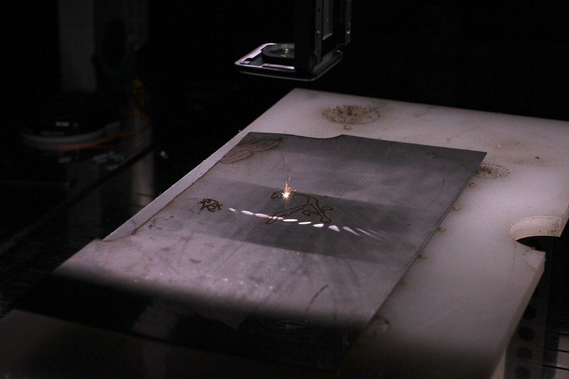
This thing is getting close to being finished. Last night I tackled controlling the laser from mach3. First I tried using the step pulse output to control the laser. I couldnt get a stable enough pulse train out of the computer for the laser to be happy. Next I tried a 555 timer and some optos. Didnt get very good wave shape out of it to make the laser happy. Finally I just used a 555 timer driven by the output signal of the breakout board to drive the laser trigger input directly. That seems to work. Took a little tweaking of the duty cycle and frequency but it looks like it will work for now. I plan on using a uC to handle the frequency generation so mach can control the power but that can wait.
I made the first cuts with it tonight. I used some 1/16" stainless as the sacrificial material. I used the roadrunner file included with Mach3 as the sample. I did a search and replace that replaced all the z-.1 with M3s and z.2 with M5s to turn the laser on and off. The scaling of the road runner files was set to .1, so the whole thing was about 7/8" wide. It ran all pretty slow due to all the tiny segments in the code.
Next I need to put the sides on an a bunch of other little things.

IMG_2603 by macona, on Flickr
IMG_2608 by macona, on Flickr

IMG_2609 by macona, on Flickr
I made the first cuts with it tonight. I used some 1/16" stainless as the sacrificial material. I used the roadrunner file included with Mach3 as the sample. I did a search and replace that replaced all the z-.1 with M3s and z.2 with M5s to turn the laser on and off. The scaling of the road runner files was set to .1, so the whole thing was about 7/8" wide. It ran all pretty slow due to all the tiny segments in the code.
Next I need to put the sides on an a bunch of other little things.
IMG_2603 by macona, on Flickr
IMG_2608 by macona, on Flickr
IMG_2609 by macona, on Flickr
- Jerry
- Posts: 573
- Joined: Sun Jul 18, 2010 12:07 am
- Location: Beaverton, OR
Re: Project: Laser Cutter (CNC)
![]() by Jerry » Tue Aug 14, 2012 8:23 pm
by Jerry » Tue Aug 14, 2012 8:23 pm
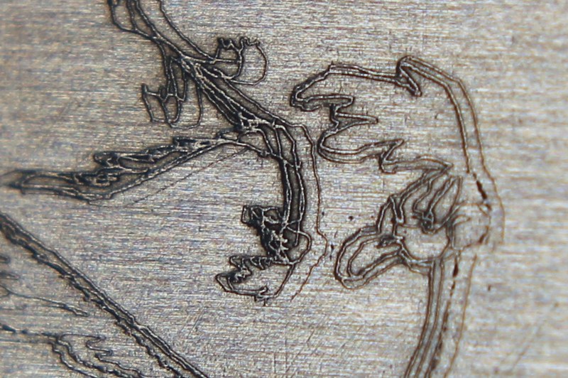
I took some pics of the engravings i did last night after i went at them with a scotchbrite deburring wheel to remove all the burnt slag:
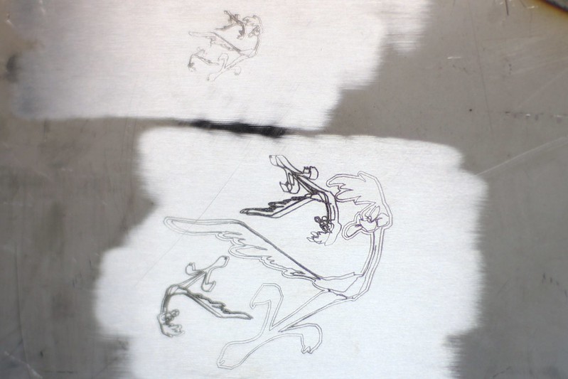
Both engravings by macona, on Flickr
Detail of small engraving by macona, on Flickr

Detail of large engraving by macona, on Flickr
Both engravings by macona, on Flickr
Detail of small engraving by macona, on Flickr
Detail of large engraving by macona, on Flickr
- Jerry
- Posts: 573
- Joined: Sun Jul 18, 2010 12:07 am
- Location: Beaverton, OR
Re: Project: Laser Cutter (CNC)
![]() by Doug Coulter » Wed Aug 15, 2012 2:08 pm
by Doug Coulter » Wed Aug 15, 2012 2:08 pm
This is simply stunning! So...what are you going to use this to do down the road, any idea? I'm presuming you can also cut all the way through reasonable substrates?
Posting as just me, not as the forum owner. Everything I say is "in my opinion" and YMMV -- which should go for everyone without saying.
-
Doug Coulter - Posts: 3515
- Joined: Wed Jul 14, 2010 7:05 pm
- Location: Floyd county, VA, USA
Return to Machining and Fabrication
Who is online
Users browsing this forum: No registered users and 1 guest