Been spending the last week or so debugging things. X axis would just take off in the positive direction randomly. But only when commanded from the parallel port. If I send move commands in the control software via serial it moves how it should. Y axis would not hold position. If I move it falls short in the return to the original position.
It turned out both problems had a common theme... Noise.
X axis was getting noise in the step line when going in the positive direction. (Why positive only, I dont know) The noise was being picked up as step signals and the axis would take off until it tripped an internal overspeed limit. Luckily there is built in filtering. I adjusted it up to match the encoder filtering and everything started working as it should.
Y axis was a bit of a pain. First I had an issue with the multiplier. When I looked at the position status in the control software it was showing some odd position data, it was not multiplying right. Seems it does funny things when it is set in nvram and program code. Eliminated the multiplier in code and it moved pretty much as it should. Still it was not returning to the same spot after a move. If I rapid moved from 0 to 5 inches it would move further and then when I return back it would come up about 1/8" short. Weird thing was the slower I ran this test the more it would be off. Normally with an encoder you loose pulses and the motion is more than commanded. This was the opposite, it was receiving extra pulses while moving so it would come up short. I took my scope and put it on the lines from the pickup head to the interpolater board and found all sorts of noise. I disconnected the motor and a lot of it disappeared. I was getting all sorts of harmonics from the PWM from the motor drives. I tried using the built in filtering but it just wouldnt cut it. While the probe was connected I took a little ceramic .01 uf cap and put it from the signal line to the frame ground. That killed about 90% of the noise. I pulled the arm board off and soldered caps from each signal line to ground. I also solder in a couple 1uf caps near the connector to the encoder on the gantry board. That seemed to fix the problem, almost. It was moving the right distance in one direction but falling short in the other. I took the scope and put it on the TTL output of interpolator board. There was a strange glitch to ground in one channel and in only one direction. I then put the scope on the 1v p-p lines from the encoder. As I moved the axis one of the channels had a glitch where it would suddenly drop out for a few microseconds before resuming. I swapped out the reader head with a new one and that fixed the last remaining problem with the Y axis. It now moves exactly where it should, at least better than I can measure, or care to. 100 steps per mm, 2000steps per sec per sec acceleration, and will do over 1100ipm.
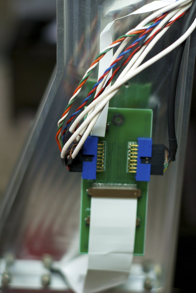
Now that I got that fixed I made up a plate to support the gantry board and guide the wires in the cable tray. Took some aluminum and milled it to the shape I wanted and mounted. I also yanked the hall effect cables from the cable bundle as they will not be needed.
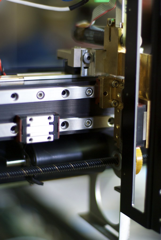
Another thing I did was to stiffen up the Y axis. It was running on single truck on the small 10mm linear rail. The truck is preloaded but it is still lacking in stiffness. There is an auxiliary rail just below it with a couple more trucks. So I took some measurements and made a small plate to tie the two trucks together, I also milled away some of the part the truck mounted to to make up for the increased thickness. Tying these two together increased the stiffness substantially.
Now that it moves how it should I have found a problem that is causing me some problems. When the X axis moves the whole arm flexes. I have traced it down to the upright support that rises from the linear bearings. Much of it has been milled away for cable pass though and lightening. This has also made it pretty weak. Normally it would be fine because the original machine probably had S-curve acceleration and deceleration which helps a lot. Mach, EMC, and all the other cheap laser controls use a trapezoidal acceleration/deceleration curve that induces a lot of "jerk" into the machine which is very apparent in this set up. The far end wobbles back and forth like a leaf in the wind!
So, somehow I need to make things more rigid. So far I have two Ideas. One is to machine some plates to fill in the hollowed out areas on the X axis arm. Bolt through and probably epoxy them into place. Then Also make a heavy lid for the back side to box it in as well as I can. If that does not work Its on to plan 2. That is using a cable/belt and pulley system to drive the other side of the gantry. Another thing that might help is replacing the round rail guide system on the undriven side with some linear rails. That ought to give it a little more stiffness.
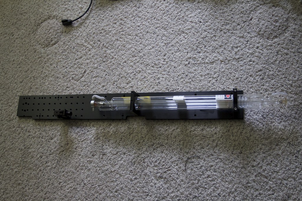
Now to a point where I need to get the laser and power supply. Also need to start scrounging up some mirrors. Its going to take more than I thought due to how I want to install the tube. Looks like I will need about 5 of them. Smaller than normal as well due to space constraints.
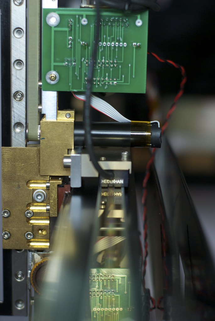
Here's a pic of the gantry board and support. The extra connectors are for things like home and limit switches.
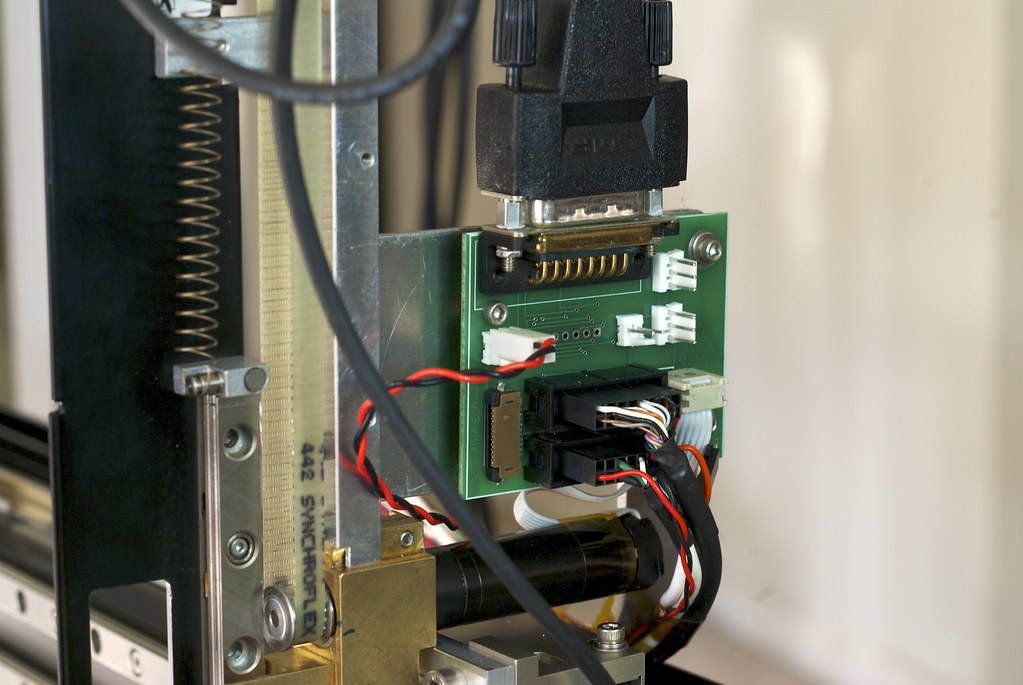 IMGP6555
 by
macona, on Flickr