Nice work Jerry
Doug CAD SW looks very much like Protel for DOS or maybe an early windows version
Project: Laser Cutter (CNC)
Re: Project: Laser Cutter (CNC)
![]() by johnf » Fri Sep 17, 2010 5:04 pm
by johnf » Fri Sep 17, 2010 5:04 pm
- johnf
- Posts: 434
- Joined: Sun Aug 08, 2010 3:51 pm
- Location: Wellington New Zealand
Re: Project: Laser Cutter (CNC)
![]() by Jerry » Fri Sep 17, 2010 7:59 pm
by Jerry » Fri Sep 17, 2010 7:59 pm
I use CircuitMaker 2000. Pretty much abandon-ware at this point. Has analog and digital simulation built in through pspice.
Found a place I can get the boards made for $25 a set introductory offer. Got to reroute the boards with larger drill sizes for the vials. I am .001 to small!
Found a place I can get the boards made for $25 a set introductory offer. Got to reroute the boards with larger drill sizes for the vials. I am .001 to small!
- Jerry
- Posts: 573
- Joined: Sun Jul 18, 2010 12:07 am
- Location: Beaverton, OR
Re: Project: Laser Cutter (CNC)
![]() by Doug Coulter » Fri Sep 17, 2010 8:11 pm
by Doug Coulter » Fri Sep 17, 2010 8:11 pm
Not bad. yeah, the layout stuff tends to be a bit optimistic on how small you can make the vias. I use APCircuits in Canada a lot, they are not that cheap, but they are both good and fast, and not too pricey. I usually make the first one here (and just solder ww wire through the vias as needed) before I send them up there. I think their record is 3 days from emailing the gerbers to getting the boards in my hand -- could be worse. I tend to use about 10 mil holes in 30 mil pads for vias when I can -- makes it easy for the board maker. I've been doing business with those guys for decades and even swapped work -- we built them an optical spectrometer with reference comparison for their baths so they could have better quality control...and I didn't pay for boards for a long time after that.
I knew it wasn't protel for dos, because that's what *I* use! Love it, too -- I also have the spendy new version (from a customer) but I hate that -- you have to have a ton of paid for parts libraries to make it go, and it's tricky unless you do only that all day long. The old one, heck, you just put down a "16 pin dip" or whatever and that's all it cares about. Has netlists etc, it's enough, dirt simple and was written for a 286, so it screams in freedos on linux to say the least.
I just never got the the hang of the crippleware Eagle or it's ilk, and the old traxedit does what I need and doesn't seem to have worn out yet.
Posting as just me, not as the forum owner. Everything I say is "in my opinion" and YMMV -- which should go for everyone without saying.
-

Doug Coulter - Posts: 3515
- Joined: Wed Jul 14, 2010 7:05 pm
- Location: Floyd county, VA, USA
Re: Project: Laser Cutter (CNC)
![]() by Jerry » Fri Sep 17, 2010 9:59 pm
by Jerry » Fri Sep 17, 2010 9:59 pm
Last weel the local dorkbot group was gifted a copy of Altium Designer with one of their development kits by one of the guys that works for them. The software license is a cloud license so it can be used on multiple machines, just one person can run it at a time. Supposed to be some really great software. Normally the package is $5000 a seat. I might have to give it a try if and when I make some other boards.
- Jerry
- Posts: 573
- Joined: Sun Jul 18, 2010 12:07 am
- Location: Beaverton, OR
Re: Project: Laser Cutter (CNC)
![]() by Doug Coulter » Sat Sep 18, 2010 6:28 pm
by Doug Coulter » Sat Sep 18, 2010 6:28 pm
If anyone is interested, I can put up a copy of Trax (protel for dos) in the library. It's freeware and gets it done for me. I do have to make the odd part for many-pin smds, but you do that once for the library and never have to again. Lots of fine control if you like odd shapes for pads and stuff. It will make gerbers for sending off, or just print on a laser for transparencies for use here, which is how I make sure I have a good board before I pay someone's setup charges. You do have to have either a real dos or a good emulator that lets it think it can talk right to hardware. Meaning windows 2k sp2 and up won't do -- they broke dos from then on. I run Virtual box here so I can kinda run anything I want, but I just use the freedos/dosemu on linux for it, works fine.
Posting as just me, not as the forum owner. Everything I say is "in my opinion" and YMMV -- which should go for everyone without saying.
-
Doug Coulter - Posts: 3515
- Joined: Wed Jul 14, 2010 7:05 pm
- Location: Floyd county, VA, USA
Re: Project: Laser Cutter (CNC)
![]() by Jerry » Thu Nov 04, 2010 10:31 pm
by Jerry » Thu Nov 04, 2010 10:31 pm
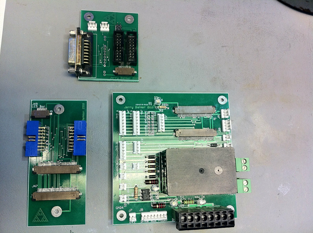
The boards showed up the middle of last month. Nice looking boards:
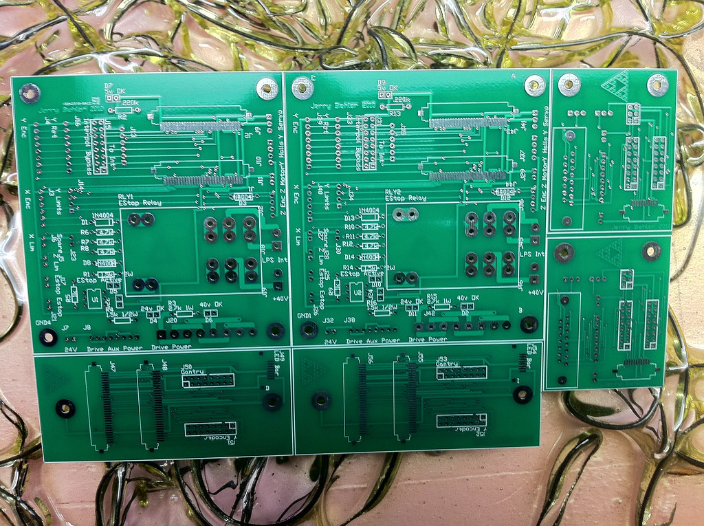
Laser cutter boards by macona, on Flickr
I ordered the parts and have been putting them together. Not too many problems. Main one was the program speced the hole for the IDC headers too small. I eventually got the connectors pushed in, but it was tough.
Big board is the main interface board. It connects the servo drives to the motors. The gantry is connected by Flexible Flat Cables which connect at the top right. This connects power, motor power, limits, and encoder feedback. The board on the left is where the FFC's terminate in the X Axis arm. From here they go to High flex silicone cables to connect the arm to the Y axis arm through the two 16pin IDC headers. They connect the Z axis motor and encoder and the Y axis encoder which are both mounted to the Y axis connecting to the Small board on top. There the heidenhain linear encoder plugs into the DB15, limits to the two white connectors and the Z motor to the little 6 pin IDC header.
The extra pads on the boards are for options like a different type of encoder on the Y axis or moving the Y axis motor to the side of the machine.
The main board also handles the estop and power distribution. The big relay cuts power to the laser power supply and the +40v main buss to the servo drives in the eventof an estop condition.
Boards by macona, on Flickr
- Jerry
- Posts: 573
- Joined: Sun Jul 18, 2010 12:07 am
- Location: Beaverton, OR
Re: Project: Laser Cutter (CNC)
![]() by Jerry » Wed Dec 29, 2010 10:31 pm
by Jerry » Wed Dec 29, 2010 10:31 pm
Did a little more work on the laser cutter. We are given the 24th to the 4th off so I have some time.
I picked up a Heidenhain IBV series interpolator for the encoder. The box that is comes in takes up way too much room so I popped out the board from the housing and am going to mount directly. The interpolator takes the analog sinusoidal quadrature output of the linear encoder and converts it to TTL quadrature. This will then provide feedback to the servo drive.
I laid out the boards today and mounted them and the servo drives as well. Now its time to start wiring. Whee...
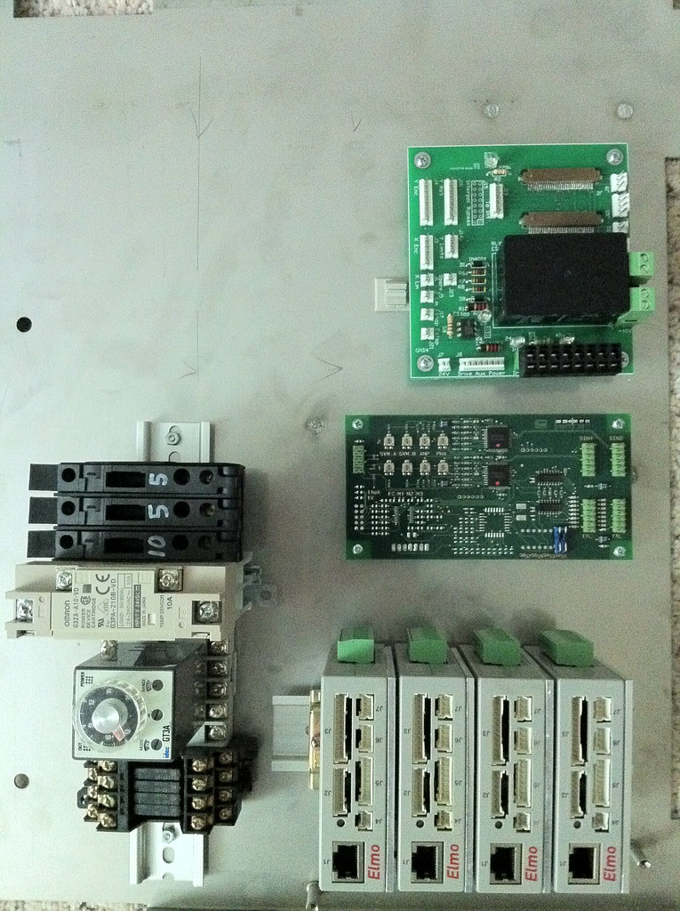
Laser cutter electronics by macona, on Flickr
I picked up a Heidenhain IBV series interpolator for the encoder. The box that is comes in takes up way too much room so I popped out the board from the housing and am going to mount directly. The interpolator takes the analog sinusoidal quadrature output of the linear encoder and converts it to TTL quadrature. This will then provide feedback to the servo drive.
I laid out the boards today and mounted them and the servo drives as well. Now its time to start wiring. Whee...
Laser cutter electronics by macona, on Flickr
- Jerry
- Posts: 573
- Joined: Sun Jul 18, 2010 12:07 am
- Location: Beaverton, OR
Re: Project: Laser Cutter (CNC)
![]() by Doug Coulter » Thu Dec 30, 2010 10:11 am
by Doug Coulter » Thu Dec 30, 2010 10:11 am
Looks like you're in for a job 'o work wiring that up and then troubleshooting any errors! I'm guessing the result is going to be way worth it, though 
Posting as just me, not as the forum owner. Everything I say is "in my opinion" and YMMV -- which should go for everyone without saying.
-
Doug Coulter - Posts: 3515
- Joined: Wed Jul 14, 2010 7:05 pm
- Location: Floyd county, VA, USA
Re: Project: Laser Cutter (CNC)
![]() by Jerry » Sun Jan 30, 2011 3:11 am
by Jerry » Sun Jan 30, 2011 3:11 am
Finally got around to start wiring it up. After doing the servo re-retrofit on the Monarch 10EE I decided its time to ditch the old brushed glentek servos on the cnc mill and install some newer Mitsubishi AC Brushless servos on the mill. This should fix several issues I have had. Now I am waiting for boards for the conversion so I have nothing to do.
The servo connections for the encoders and stuff are a pain in the rear. the crimp on pins are a little over 3/16" long. Not designed to be hand crimped!
I too a set of the boards and set them up on the machine to ring things out to make sure I didn't screw up somewhere. I measured from ground to the ground on the x axis encoder, good, +24 to the encoder, good, same to the board arm, all good. Check continuity across gnd and +24, Uh-oh shows a dead short. After a bit of freaking out I found one of the flexible flat cables was loose in the connector and was pulled out at an angle shorting the two adjacent lines. Scared the crap out of me...
So most of the motor stuff is wired now. I still need to wire in the interpolator. But at this point I think I am ready to hook up the drives to power and start setting some of the parameters.

IMGP6514 by macona, on Flickr
The servo connections for the encoders and stuff are a pain in the rear. the crimp on pins are a little over 3/16" long. Not designed to be hand crimped!
I too a set of the boards and set them up on the machine to ring things out to make sure I didn't screw up somewhere. I measured from ground to the ground on the x axis encoder, good, +24 to the encoder, good, same to the board arm, all good. Check continuity across gnd and +24, Uh-oh shows a dead short. After a bit of freaking out I found one of the flexible flat cables was loose in the connector and was pulled out at an angle shorting the two adjacent lines. Scared the crap out of me...
So most of the motor stuff is wired now. I still need to wire in the interpolator. But at this point I think I am ready to hook up the drives to power and start setting some of the parameters.
IMGP6514 by macona, on Flickr
- Jerry
- Posts: 573
- Joined: Sun Jul 18, 2010 12:07 am
- Location: Beaverton, OR
Re: Project: Laser Cutter (CNC)
![]() by Jerry » Mon Feb 07, 2011 8:22 pm
by Jerry » Mon Feb 07, 2011 8:22 pm
I made some more progress this week. It was too darn cold in the garage to do any work so I got a friend to help me bring the gantry inside. Now it sits on my living room floor.
I got the bottom plate with the electronics bolted down and the power supplies mounted and wired in. Checked connections and everything seems to be OK. Eventually found two little issues. The stock board that the encoder on the X axis connects to and where the flex flat cables (FFC) terminate to before going to the arm had pins 26 to 30 on one of the two connectors ending in the board. This killed my 5v power to the gantry among other things. I jumped the connectors with some 32 ga wire and that fixed that. Second problem was the connection for the brushless motor on the Y axis. I got the pin order backwards. 1 was at 11 and 11 at 1. Luckily I was able to peel off the back spacer of the FFC and fold it over. I made up cables to connect the arm board to the carriage. I used those silicone wires I had posted about earlier. Pretty much the perfect length. I also made up a cable for the encoder, used some nice renishaw 12 conductor double insulated encoder cable that I picked up off ebay years ago.
I then made up a cable to connect the RJ45 serial connectors on the drives to the serial port on a laptop and installed the software for the drives. I managed to get the X axis tuned using the auto tune function, moves pretty quick with a resolution of .01mm per step. I dont have the encoder on the Y but managed to get it working in a low res mode where it reads the feedback from the motors hall encoder.
The Z axis motor was not so kind to me. Its a little maxon gear head motor. .18 amps at 45volts, 32 count encoder on the back, 24:1 gear box on it. First problem is the drive would not accept the single ended input from the stock encoder. Most drives have differential signaling built in and will take a single ended encoder input. Not these. I tried cheating and it almost worked but there was a whole lot of noise in the signal and it would not work right. So I needed to change the single ended input into a differential signal. Normally you would use a line driver but I didnt have one. What I did have was a mechanically bad encoder with line driver outputs. I took the board out and there was a line driver chip. I removed all the other components and took the bandsaw to the extra circuit board. I wired a connector to the inputs of the line driver IC and put a connector for the servo drive on the other end so the board is between the motor encoder and the servo drive. Finally the drive is happy.
Still problems though. Seems the motor draws less current than the drive really likes to see. This means the auto-tune is not happy. So I spent about 2 hours tuning the drive manually. Looks like this should work now.
Next up is trying to figure out how to mount the Y axis encoder scale and come up with a better mount for the Y servo motor. This one is just too floppy.
Here are a couple pics. One with the electronics mounted to the machine and the other with the machine guts exposed at night. I think I used too bright of LEDs!

Laser cutter electronics by macona, on Flickr

Laser cutter at night by macona, on Flickr
I got the bottom plate with the electronics bolted down and the power supplies mounted and wired in. Checked connections and everything seems to be OK. Eventually found two little issues. The stock board that the encoder on the X axis connects to and where the flex flat cables (FFC) terminate to before going to the arm had pins 26 to 30 on one of the two connectors ending in the board. This killed my 5v power to the gantry among other things. I jumped the connectors with some 32 ga wire and that fixed that. Second problem was the connection for the brushless motor on the Y axis. I got the pin order backwards. 1 was at 11 and 11 at 1. Luckily I was able to peel off the back spacer of the FFC and fold it over. I made up cables to connect the arm board to the carriage. I used those silicone wires I had posted about earlier. Pretty much the perfect length. I also made up a cable for the encoder, used some nice renishaw 12 conductor double insulated encoder cable that I picked up off ebay years ago.
I then made up a cable to connect the RJ45 serial connectors on the drives to the serial port on a laptop and installed the software for the drives. I managed to get the X axis tuned using the auto tune function, moves pretty quick with a resolution of .01mm per step. I dont have the encoder on the Y but managed to get it working in a low res mode where it reads the feedback from the motors hall encoder.
The Z axis motor was not so kind to me. Its a little maxon gear head motor. .18 amps at 45volts, 32 count encoder on the back, 24:1 gear box on it. First problem is the drive would not accept the single ended input from the stock encoder. Most drives have differential signaling built in and will take a single ended encoder input. Not these. I tried cheating and it almost worked but there was a whole lot of noise in the signal and it would not work right. So I needed to change the single ended input into a differential signal. Normally you would use a line driver but I didnt have one. What I did have was a mechanically bad encoder with line driver outputs. I took the board out and there was a line driver chip. I removed all the other components and took the bandsaw to the extra circuit board. I wired a connector to the inputs of the line driver IC and put a connector for the servo drive on the other end so the board is between the motor encoder and the servo drive. Finally the drive is happy.
Still problems though. Seems the motor draws less current than the drive really likes to see. This means the auto-tune is not happy. So I spent about 2 hours tuning the drive manually. Looks like this should work now.
Next up is trying to figure out how to mount the Y axis encoder scale and come up with a better mount for the Y servo motor. This one is just too floppy.
Here are a couple pics. One with the electronics mounted to the machine and the other with the machine guts exposed at night. I think I used too bright of LEDs!
Laser cutter electronics by macona, on Flickr
Laser cutter at night by macona, on Flickr
- Jerry
- Posts: 573
- Joined: Sun Jul 18, 2010 12:07 am
- Location: Beaverton, OR
Return to Machining and Fabrication
Who is online
Users browsing this forum: No registered users and 5 guests