Quiet compressor project

Stuff you made and how to make cool stuff

Quiet compressor project

Postby Jerry » Wed Aug 04, 2010 10:33 pm

Did this last night:

On my RGA system there are two valves the select between wide open and the orifice for high pressure sampling. They are both air operated so I needed something to operate them. I bought one of the 2HP (Yeah, right) little compressors from Harbor Freight years ago. Noisy darn thing. I needed something quieter!

Image

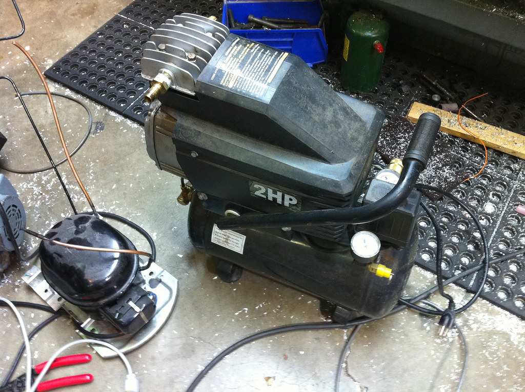
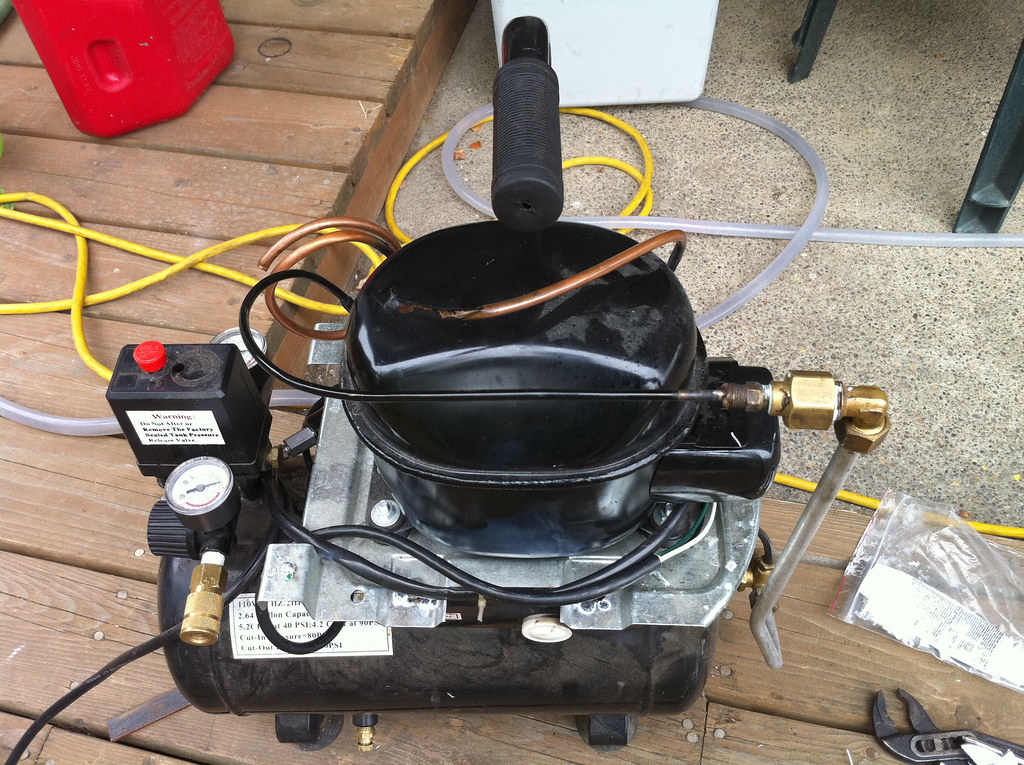
A friend of mine has one of the little Jun-air compressors. They are basically a refrigeration compressor on a tank. The only real difference is the compressor is meant to be able to be worked on. So I figured I would do something similar. I yanked a small hermetic compressor out of a water cooler and welded its mounting bracket to the existing bracket on the compressor tank. Silver soldered on a fitting on the end of the output line and adapted it to the existing line. The only real problem I found is the compressor does not have enough volume to close the unloader valve on the pressure switch. I installed a N.O. 120v solenoid valve in parallel with the motor and connected to the existing unloader line. That has seem to have done the trick. Set the pressure to kick out at 100 PSI. Has no problem getting up there. And most importantly is very quiet!

But it is really slow! I may yet stick a larger pump on there. We'll see. Not like I need it for much. I have a very nice Powerex oilless scroll compressor in the shop.

Yes, I know about lubrication on these pumps. If it goes bad Ill grab another from the scrap yard.

Image
Jerry
 
Posts: 573
Joined: Sun Jul 18, 2010 12:07 am
Location: Beaverton, OR

Re: Quiet compressor project

Postby Doug Coulter » Wed Aug 04, 2010 10:50 pm

Yeah, I had one of those noisy ones and ditched it fast -- gave it away to a poor motorcycle mechanic, and not sure if I did him a favor or not. Good old slow belt drive one is what runs my shop now.
Even that I put in the crawl space to keep that noise down, vibration, and save some floor space in the shop proper.

I guess I'm not understanding why you're not using shop air, either direct or from a pressure bottle -- don't the valves take only a little air to operate? I must be missing something here.

Before I got AC power here, and while I was otherwise flat broke too, I used a fairly cheap surplus 24v DC one I got surplus, oil free 2 piston type. It got me by and wasn't too noisy. Nice fat DC servo motor on it, which I may rescue for something else, as it was pretty efficient. Didn't have much flow, but I had it on a big tank, so after some minutes I had pressure and enough to work the odd air tool for a little bit before waiting again.
Of course the current that thing drew at 24v was kind of hard on the air pressure switch.

If oil in the air doesn't worry you too much, you might arrange for a bit of reservoir in the output line, above the compressor so it would drain back down into the works?
Posting as just me, not as the forum owner. Everything I say is "in my opinion" and YMMV -- which should go for everyone without saying.
User avatar
Doug Coulter
 
Posts: 3515
Joined: Wed Jul 14, 2010 7:05 pm
Location: Floyd county, VA, USA

Re: Quiet compressor project

Postby Jerry » Thu Aug 05, 2010 1:56 am

The spare bedroom where I have my "lab" set up is at the furthest point from the garage where the shop compressor is. I could run it on the argon or nitrogen I will use for purging but I need to get down to airgas and get a fill. I also want the compressor for when I get a desoldering unit for my metcal. It needs 75psi to run. Also makes a nice light compressor for my airbrush.
Jerry
 
Posts: 573
Joined: Sun Jul 18, 2010 12:07 am
Location: Beaverton, OR

Re: Quiet compressor project

Postby Doug Coulter » Thu Aug 05, 2010 8:27 am

Ah, well perhaps I'm lucky with that one -- no place in this building is farther than about 6' from an air outlet. I was fairly flush when I built it, and plumbed air to both sides of both floors using copper pipe with tap-offs at every workstation and a couple places on the ends too. I used 3/4" pipe downstairs and 1/2" pipe upstairs, in loops around the walls at ceiling height, and that alone is quite a reservoir. Not much water in the air upstairs...Not much downstairs either since the compressor is beneath the floor, and things were laid out to drain condensation back to the main tank down there (which reminds me of the main reason not to have the compressor out of sight -- I gotta go let the water out, stat!)

Did you say you have a Metcal soldering station? I do, and I love that thing. Makes putting down SMD's easier than through-hole on PCBs. I would never have thought a $2.5k soldering station could ever be worth it (at least to this old Scot), but I was wrong. I was taught this by two exceptional women who did all the proto and rework for a large customer who made telephony and paging gear in a multi acre robotic factory near here. They really showed me the ropes, and heck, I could already solder two things together in the palm of my hand without getting burned....but they kicked my butt around the block, showed me the right tools, tips, flux, and so forth. They had tried it all, and this is what they wound up with. Kester 952 is almost magic...

Yeah, for an airbrush we tried the common little piston compressors, fairly low pressure (20 something psi) an the pulsating flow didn't help that a bit, we now use an inline regulator off the shop air for that. But I must say that the pulsating flow works out nicely in my powder coat guns, particularly when the air is a bit damp.
Posting as just me, not as the forum owner. Everything I say is "in my opinion" and YMMV -- which should go for everyone without saying.
User avatar
Doug Coulter
 
Posts: 3515
Joined: Wed Jul 14, 2010 7:05 pm
Location: Floyd county, VA, USA

Re: Quiet compressor project

Postby Jerry » Thu Aug 05, 2010 1:11 pm

I have two metcals, One of the MX500 stations and one of the SP200s. The MX500 blows the SP200 out of the water!

Interesting thing, the MX500 runs at 13.56MHz and the SP200 at 450KHz. What do you think, hook it to that big 450KHz RF supply I have??? :D
Jerry
 
Posts: 573
Joined: Sun Jul 18, 2010 12:07 am
Location: Beaverton, OR

Re: Quiet compressor project

Postby Doug Coulter » Thu Aug 05, 2010 2:52 pm

I think it needs regulation in it's little RF supply to live or something IIRC how they work.

Mine's a 500 too, with a single and a tweezer hand-pieces. I mostly use the single with the "horse hoof" tip to put down big quad flatpacks, and the tweezers to lift little SMD discretes.
That horse hoof thing is awesome. I flux with Kester 952, put the part down, tack a corner or two to hold it in place (just heat a lead), put a tiny amount of solder on the tip, wipe along the whole row of pins, it's done, stick a fork in it.

I lay my boards weird to make this work the best. I make the pads just a little narrower than the chip pins. That way if you get a bridge, it's always pin to pin, and easily sucked out with wick, or most often just a flick of a clean iron tip. They go the other way when using solder paste and mask I hear, but this is what works best for short runs done manually. What I find is that with AP Circuits, the cheap proto I (no solder mask) already has enough solder plating on it to do the job, or nearly. If you get the "better" proto II service, the fact that the mask is thick makes it a little harder for the pins to get down into the solder plating, which is also thinner on that process.
Posting as just me, not as the forum owner. Everything I say is "in my opinion" and YMMV -- which should go for everyone without saying.
User avatar
Doug Coulter
 
Posts: 3515
Joined: Wed Jul 14, 2010 7:05 pm
Location: Floyd county, VA, USA

Re: Quiet compressor project

Postby Jerry » Thu Aug 05, 2010 11:57 pm

Its pretty interesting how these metcals work, and the ones that have copied them. The cartridge has a coil of 36 ga wire wrapped around the tip, rf is applied to the coil and the tip is inductively heated. The tips material is selected by its curie temp. When it gets to this temp the circuit goes out of tune and stops heating. The station senses this (I assume through reflected power) and turns back the power. The advantage of this design is no thermal sensor that can break or go bad is necessary, nor is calibration required. It also keeps the mass of the tip down so it faster to heat and react to thermal load. Tips still do wear out though. They take longer to heat up when they get old.

If you ever need schematics for your 500, I have them. There is only one part in there that really cant be replaced, one of the main power transistors in the oscillator.
Jerry
 
Posts: 573
Joined: Sun Jul 18, 2010 12:07 am
Location: Beaverton, OR


Return to Machining and Fabrication

Who is online

Users browsing this forum: No registered users and 27 guests