 Here is a picture that to us is historic. This was our first sucessful run in the sense of making enough neutrons to make counters count and BTI detectors bubble. Bill Fain is being brave to stand there, as the HV is on in this picture, and he's pretty close to it. The DVM in the picture is showing the voltage in kV -- we backed it off to take the picture at higher gas pressure to get more light output, but we are still making some neutrons and X rays. The scope is looking at the output of the RemBall plus noise on the upper trace, and noise plus Gamma spectrometer head on the lower trace.
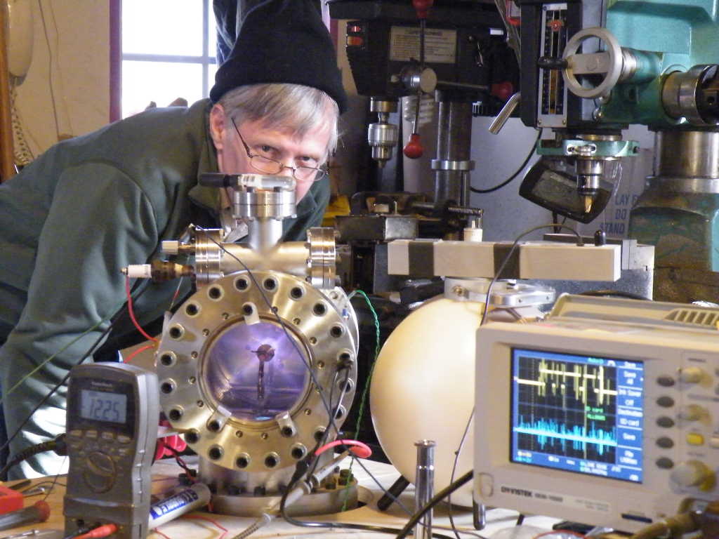
We are using deuterium from electrolyzing heavy water in this run, an old cranky X ray power supply that took well over 300 watts input at no load to make 16kv (transformer saturation even with 2khz drive) and in this case an arcing ballast resistor. The deuterium is allowed into the tank via the valve knob you can see next to the spark plug feedthrough, which was used to power the gas-dynamic ionizer we were using at the time. The HV is coming in at the back of the Tee, about where Bill's chest is. The BTI detector on top of the tank is showing a few bubbles from this run. Not exactly a ground-breaking amount, but our first no kidding real neutron output from any system here, and this one is Bill's personal system. The little chrome thing in front of the rem ball is a handheld spectroscope we got to check the purity of the D we were producing, and in fact is something we recommend everyone get -- cheap, and a poor man's RGA once you get a little bit of experience interpreting the lines you see in it.
Setup description:
Vacuum: Mech two stage pump, 1 hp, Varian water cooled 3" diffusion pump running on about half rated power input with Diffoil 20, cool (water) trap, large gate valve for throttling.
Power: Cranky old X ray supply, barely worth it to fire up, running on a 500w Bogen audio amp at 2khz to avoid transformer saturation, sort of, never worked really good, running in a kitchen trashcan full of mineral oil once we cleaned off the PCB oil it came in. We used 60k of ballast resistors which were burning up at the time, it was a bunch of 10k 10W wire wounds in series. This setup would produce a lot of power, however cranky it was, and at 20kv and 20ma, we got a pretty decent neutron output for us at the time, before things in the tank began to melt. It seems the particular X ray supply we got was designed to run out of saturation only at full load, even with the 2khz drive (the self resonant frequency of the transformer). We'll probably ditch the transformers and use the CW stacks for something better soon.
Instruments: REM ball, we are looking at the LSB of the counter, NaI:Tl spec head, raw on scope, BTI bubble detector, 33 bubbles/mrem, 25 mhz GWInstek scope, homebrew uncalibrated Pirani gages, repeatable enough for this work.
Grid: 8 Ti wires between Ti endcaps, supported on glass rig made here, 7/8" diameter, about 3" long active area.
Observations: This was indeed early times, just getting everything working at the same time was fairly challenging. We were cooling the diff pump with a fountain pump from Lowes in a 5 gal bucket and having to add blue ice to that periodically, the cranky X ray supply just wouldn't be driven to anything like its 40kv at over 100 ma specs (this was from a welding inspection machine, and was half of the supply) without serious power waste in the too-small iron meant to only be used in pulse mode, and our ballast resistors tended to open up internally and arc (which, looking back on things, is the first time the apple hit us on the head and started us thinking about dynamic behavior and time dependence of the HV input to fusors). Later analysis on my system with the mass spectrometer indicates we were running about 30% D out of the electrolyzer, the rest being water, air, heavy water, and so forth. But as an "existence proof" of "can this be done in a home lab", yup, this was it. We did it, and subsequently did it over and over, improving things, mainly for reliability, as we went.
Operating this thing was like trying to fly two helicopters blindfolded with your feet while wearing boots, one of them upside down. I could do it, kind of, Bill could kind of, but no one could get it stable -- you had to sit there and constantly make tiny changes in gas flow and power input to keep it going in any kind of decent fashion. One important observation we made here is that there is a basic instability when running near the edge of the Paschen law. What appears to happen in most fusors is that if you have enough gas in there to light it off with the HV you've got, it's too much gas to run the thing. When the fusor becomes its own best ion source, it ionizes all the gas in the tank over a second or so time period, which means it draws more and more current, dragging down the supply (if you are lucky and don't just burn things up instead). So you open the throttle valve to the pump, and try not to overshoot to get back to the right gas pressure to run, versus just light off, so the volts will come back up. Overshoot just a tiny amount, it goes out and you start over again. With those long and variable time constants (gas flow and ionization status) this is truly something only the most skillful can do at all. If you think that's bragging, just go try it yourself. We see this on most all runs, the light off, too much gas/ions for the supply, then back down the gas pressure, then keep it lit. Much easier to do with even a minimal ion source so you don't have to start as high a pressure to get it lit in the first place, and can use smaller control variations. It would have helped a great deal to have something better than a gate valve on the diffusion pump and a better ion source, not to mention nearly any of the better HV supplies we have now. But this was enough to prove we weren't completely wasting our time and money. We_Made_Fusion! Not very much, but at all. I dunno about Bill, but I popped a couple of corks over that one. (Don't believe Bill drinks anything but water)
Something very important happened during this run, and a couple after that (and still). We went into a pulsed mode, not on purpose, but because of a bad connection/ballast in the input power. At some point, we noticed that with the HV going up and down, we only got counts on the REM ball during onsets. On the scope, we saw noise with no neutrons, but never neutrons without that power supply noise. Yes, I can hear those with some experience with EMI saying we were just counting our own noise on the REM ball. Sorry guys, I am expert at this kind of thing myself (decades as an EE in signal extraction and processing) and that wasn't what was happening at all. For one thing, where did those BTI bubbles come from? EMI doesn't do that.
Further, the REM ball only counted on onsets, not dropoff of HV and the FFT spectrum of the EMI was the same either way. And this has since been duplicated on all different gear and in no case do the sensors see neutrons unless there is deuterium in the tank, noise or not. There is something very special about getting time bunching of the reacting ions. In my opinion, this was nature hitting us on the head with that apple, or handing us that petri dish that had the odd mold that killed off the desired culture -- all we had to do was pay attention to things unexpected to "get it". And we did both. We have now found a number of pulsed modes that give far higher Q than the normal fusor does, and are pursuing that actively.
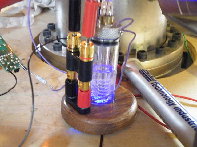 Here is what we used for fuel. This electrolyzer is more or less copied from
Andrew Seltzman's design, and here is running on about 12 volts with a series resistor, and a UV LED in series -- pure kark, I know, but cool looking, eh? You can also see the CCFL inverter used to power the ion source in this picture, just horse-wired and hanging in air, running off the same 12 volt supply down in the rack this is built on. We baked out some NaCO3 to dry it, added it to the heavy water so it would draw current and electrolyze, and it works pretty well if you can tolerate all the other stuff it puts out. The gas proceeds to a cheap needle valve from
McMaster-Carr and then through a piece of capillary tubing to the gas-dynamic ion source I designed/invented, which will be described elsewhere on the site as "interesting but not as good as what we now use" in the construction projects section. At any rate, though not perfect, these things were good enough to get us to the starting line.
Here is what we used for fuel. This electrolyzer is more or less copied from
Andrew Seltzman's design, and here is running on about 12 volts with a series resistor, and a UV LED in series -- pure kark, I know, but cool looking, eh? You can also see the CCFL inverter used to power the ion source in this picture, just horse-wired and hanging in air, running off the same 12 volt supply down in the rack this is built on. We baked out some NaCO3 to dry it, added it to the heavy water so it would draw current and electrolyze, and it works pretty well if you can tolerate all the other stuff it puts out. The gas proceeds to a cheap needle valve from
McMaster-Carr and then through a piece of capillary tubing to the gas-dynamic ion source I designed/invented, which will be described elsewhere on the site as "interesting but not as good as what we now use" in the construction projects section. At any rate, though not perfect, these things were good enough to get us to the starting line.I think we maybe made 0.1 millirem in about 10 minutes running, but that only included maybe two minutes of actually running on the sweet spot, drifting in and out; either it would go out, and have to be re-lit, or it would get too much gas, drop the power supply to its knees, and only spend a little time in between, very dicey to run this at all. But one fantastic learning tool! We have since used this setup to test a variety of grids and other things from power supplies to ion sources. Having more than one fusor here (We have 3 total) means you can do real controlled experiments, where just one thing is changed between runs for comparison, without also holding back innovation too badly -- because there are those other two fusors not involved in that kind of careful, controlled testing that some new idea can be put into and tried right away while the inspiration hasn't faded.
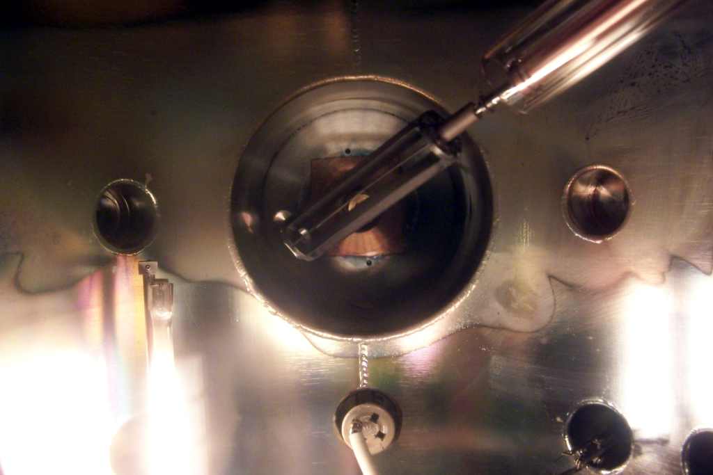
 This setup has allowed us to make quite a number of interesting observations. Here we see a run with a different grid, one that is supported in the near end by a hollow ceramic tube. You can see ions streaming out, as though there was what amounts to a compression ratio involved here -- the E field along this axis is low, the tank end with the window is far away. What we might be seeing here are a couple of things. One is a transition from molecular flow outside the grid to viscous flow inside, and thermalization in that viscous flow region, which is leaving enough ions as still ionic for them to repel themselves out of the grid end.
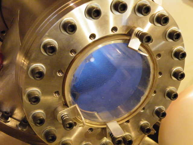
 For those interested in mere construction details, this is a great shot of the homebrew window and mount. I took this adapter flange, added an O ring groove, the viton O ring, the piece of pyrex from McMaster-Carr, and the spring clips you see here. Works great, doesn't leak, gives quick access for that "build a ship in a bottle" job we all face a lot. The flange we made for the other end of this tank is similarly easy to remove for full access to the system innards. Key if you're serious about this. If it is hard to try new things, well, are you really a serious experimenter trying to get as much done and learned as possible? Or should you fix your design so it's easy instead? Perhaps it's just my engineer ego, but this system is a good example of design. You can go from running, through opening the tank, changing something, and back to running in under 10 minutes with this and the other design features that let us keep the diffusion pump hot and ready during that time, and pump "around it" to get the system back into diff pump range before going to high vacuum again. Works very sweet, even if it does remind one of running an old steam locomotive with garden hose valves that aren't labeled. Captain Nemo is one of our fashion design consultants, after all. He says to work in some more polished brass somehow.
 Various considerations lead us in a couple of directions in grid designs. The first was accuracy of grid element placement, of the grid as a whole and the individual parts. It has been pretty obvious all along that focus matters more to net luminosity than most other things could, and no way you are going to get that with inaccurate lens elements. And in a fusor, we are making a lens, like it or not, why not make it a useful one? Other thoughts lead to the idea of using more than one grid, which is still in process here. A key insight on this is to think of a fusor as an inside-out beam power electron tube -- with positive particles going slower for voltage than in a 6L6GB for example. Many of the same concepts apply, though the scaling factors are all different. Doing this allows us to use the math worked out before most of us were born to great advantage. The first idea here is that the control grid, in this case the outer one, can intercept particles at low energy and not be heated, saving waste were those same particles to hit the inner grid (analogous to the screen grid in that beam tube) at much higher energy. Later on thinking developed further in the time bunching area and having separate positive control of the ions after they pass through the center grid, to enhance recirculation. More on that on the theory page (which I have yet to write, I will add a link here when I do).
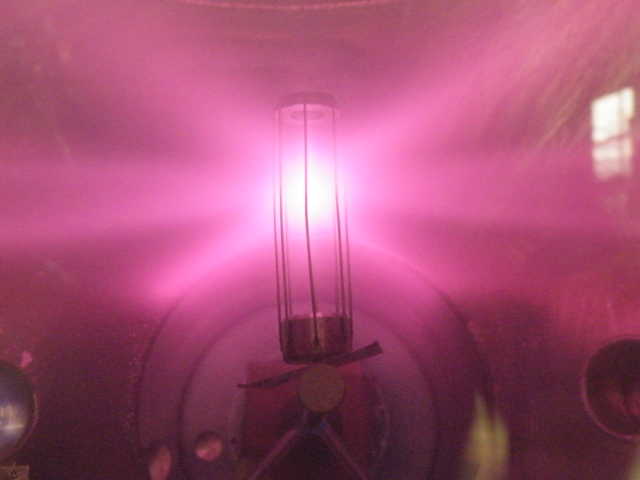
This picture is a two grid setup running in fairly high pressure He (cheap and easy compared to where we were with supply of deuterium at that point). This setup ran 1-4kv on the outer grid, and the high voltage on the inner, both grids are vane type to make better lens elements. You could think of this or most any cylinder grid arrangement as an array of cylinder lenses, one per gap between the wires, or vanes, that all have to focus at a common center for maximum luminosity at the intersection zone. Another way to look at this lashup, with an outer grid at lower HV, is to consider it doing the function of the space charge grid in an electrometer tube, producing a virtual cathode when in an electron tube, a nice uniform space charge you can then do other things with, using statistics to make variations in the space charge density smooth out.
One thing I find interesting about this picture is how good the focus is despite the very high pressure we were running -- well into viscous flow range. Despite all the scattering off too much gas in there, it still looks pretty good. The wire you can see sticking up there is an ersatz Faraday probe. Gotta get that onto a wobble stick! Stat! We did a charged particle/X-ray pinhole camera on the larger system, later, which has its own charm. One thing we found with this two grid system in other tanks of varying outer sizes is that I simply mis-guessed at the ideal grid dimensions here if what I wanted was really good focus at the focal point. This setup has made plenty of neutrons in this and the other tank, but hasn't won the records yet either. And you can see why in some pictures later on. The central focus just isn't there correctly when the volts are high enough for good fusion cross sections. Hey, oops - hope that counters a little of the bragging. We try things and learn, right?
////////////////////////////////////////////////////////////////////////////////
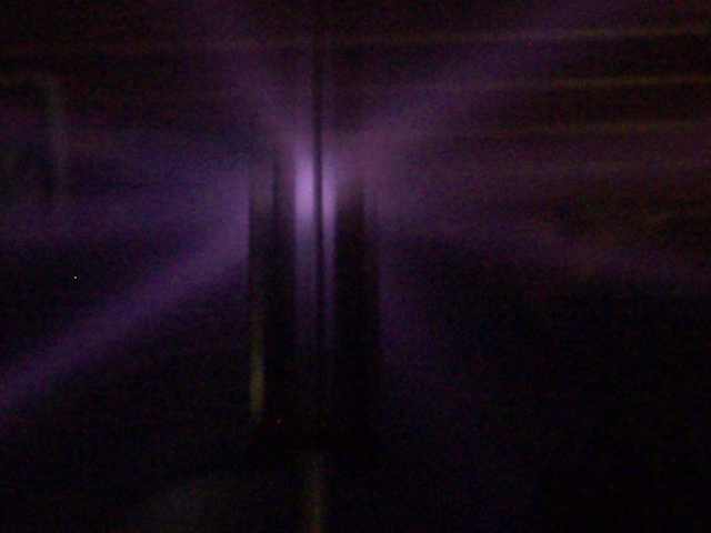
 Ah, the luxury of having more than one way to try new things. Maybe even more than one at a time! Here we see two grids in the larger system. One is diagonal, with vanes, and is the inner grid used in the picture above. The other is a wire grid back in the 6" ID stub on the big tank. I wanted to see some effects of field gradients in various outer tank sizes. The big surprise here was that even at that odd angle, the rays and so forth were symmetric and not seemingly affected by the odd placement. Seems that if the tank walls are that far away, it doesn't matter as much. It shouldn't have been a surprise that we could run lower pressure/higher voltages easier with the diagonal grid in the big space -- Paschen's law works here. The upshot though was that the wire grid was better in either place than the misproportioned vane grid. It looked good on paper, and the idea may still be a good one, but these particular samples, the wire grid is just plain better. Something this makes me think we should have tried would have been to use the grid in the bulk tank volume as an ionizer for the system....gee, that'd be easy to try! I will do it at some point.
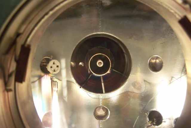
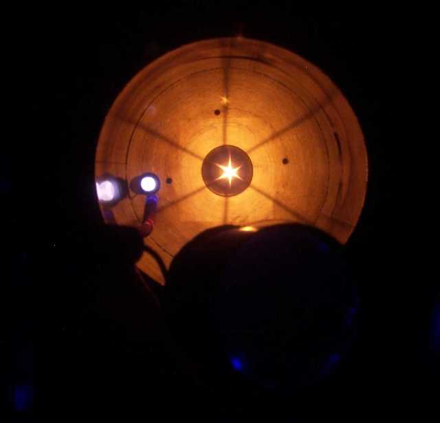
 Here is that vane (inner, smaller) grid rigged to be vertical in the middle of the 14" ID main tank. As you can see, focus is lousy, though it's a bit better when in a 6" OD thing. Here we can see an instance of the rays acting in this interesting way - coming from a point, not sheet beams. Other grids tried, even with fairly bent wires (1/8" errors) do this too. But various proportions do make far better visual focus. Whether that means better focus for the more important particles which you cannot see by definition (at these energies, only electrons can make visible light, so you are NOT seeing ions here, but excited neutrals), is unknown, but at present there does seem to be some correlation.
 So you can see the setup better, here's another grid running in an argon/air mix during pumpdown. Not too much to say about this other than "interesting" as we still see the nearly point source of the rays, and it doesn't seem affected by the bent wires all that much.
To me, that meant that one out of focus lens looks a lot like another -- out of focus. We did get some neutrons with this too, nothing special though. This was nearly the last test we made using factory HV feedthroughs. The expensive ones are easy to kill with arcs and sputtering that won't clean off of them. So we made our own, and plan to do so from now on.
So you can see the setup better, here's another grid running in an argon/air mix during pumpdown. Not too much to say about this other than "interesting" as we still see the nearly point source of the rays, and it doesn't seem affected by the bent wires all that much.
To me, that meant that one out of focus lens looks a lot like another -- out of focus. We did get some neutrons with this too, nothing special though. This was nearly the last test we made using factory HV feedthroughs. The expensive ones are easy to kill with arcs and sputtering that won't clean off of them. So we made our own, and plan to do so from now on.
 As part of our sometimes methodical approach, and based on the thought that perhaps the ratio of grid size to outer electrode size could affect focus and other parameters, we tried this. It was easier than making more grids at that point to simply put a reducing grounded tube in the tank around the grid and try that. Though there is a lot more work to do here, our takeaway from tests on this seemed to be that the 1" grid with 6" tank seemed to be a sweet spot, if not the sweet spot. This setup worked, but not very well. We had to run higher pressures and/or higher voltages to get this to go at all, things got hotter, not many neutrons, but it was worth a shot.
 To really learn what we set out to learn on this series, it would seem we have to make a grid with about the same 1::6 size ratio, but tried in the larger 14" ID of the main tank. Now, where did I put the other 50 hours I wish every day had in it? My current guess is that this would mostly be a scaling issue when we want more neutrons per setup, not a Q-affecting issue so much, but something to consider when we just want MORE. For now, the Q improvements are the main focus (pun intended), and we are already making an amount of neutrons that makes us a bit uncomfortable to be near our setups during a run. Getting more will mostly be of interest when we have gain, not for now -- the lab is entirely too close to the bedroom for that.
 Many of the tests we have made in the big tank haven't had especially impressive results (but some have been spectacular!). That's fine, what we are after with this series of tests is simply to get that all important gut feel for how it all works together.
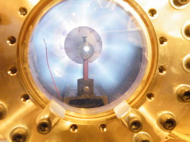
For fun, we did our best attempt to duplicate the grid Richard Hull used to make his great runs at the 2009 HEAS meeting. Here is the result. We did get some neutrons, not very many. One takeaway from this is something every topologist knows -- "you can't comb the hair on a sphere" is the colloquial shorthand for it. You can see that since there is actually no way to keep the wire spacing equal in all directions when tiling a sphere with inter wire holes, there is at least one place where they get close, and this place collects loss hits from ions preferentially, as well as the places near it having different E lens focal lengths there than where the wires are farther apart. Hey, for all you stuck in the "religion of the sphere", we did try. They don't work as well. Now this picture exaggerates how bad they are by comparison, in a futile attempt to get some kind of decent neutron output at 40kv/10mA, or thereabouts, we tried all kinds of power feeds and gas pressures, and this was at high volts and low gas pressure (eg also low current), where the effect of ions just hitting the wires kind of maxed out. We must have missed something, as we also witnessed Richard's very successful run in a spherical tank, and it wasn't nearly as bad there. This at best made about 1/4 the neutrons he did, so obviously there are other issues here and more work needs to be done to find out just what they are.
Many of the tests we have made in the big tank haven't had especially impressive results (but some have been spectacular!). That's fine, what we are after with this series of tests is simply to get that all important gut feel for how it all works together.
For fun, we did our best attempt to duplicate the grid Richard Hull used to make his great runs at the 2009 HEAS meeting. Here is the result. We did get some neutrons, not very many. One takeaway from this is something every topologist knows -- "you can't comb the hair on a sphere" is the colloquial shorthand for it. You can see that since there is actually no way to keep the wire spacing equal in all directions when tiling a sphere with inter wire holes, there is at least one place where they get close, and this place collects loss hits from ions preferentially, as well as the places near it having different E lens focal lengths there than where the wires are farther apart. Hey, for all you stuck in the "religion of the sphere", we did try. They don't work as well. Now this picture exaggerates how bad they are by comparison, in a futile attempt to get some kind of decent neutron output at 40kv/10mA, or thereabouts, we tried all kinds of power feeds and gas pressures, and this was at high volts and low gas pressure (eg also low current), where the effect of ions just hitting the wires kind of maxed out. We must have missed something, as we also witnessed Richard's very successful run in a spherical tank, and it wasn't nearly as bad there. This at best made about 1/4 the neutrons he did, so obviously there are other issues here and more work needs to be done to find out just what they are.At any rate, we were just using the big, very convenient system to try any and everything, to later put back in the smaller one for really careful parameter sweeps and minor tuning changes. Going back and forth also helps us prove (or find out about) things that are different about them, find any errors in the otherwise independent measurement systems, and so on. A luxury, indeed. Or maybe a requirement, we're not in this just to be the coolest kids on the block, we want real progress towards gain.