Pirani gauge:
Coulter's Smithing Home.
This was originally inspired by this link:
Thermister vacuum gauge
which gives some good information about how to do things like this
and what to expect. Go ahead, read it, we will wait. There's
information there that won't be duplicated here. Thanks are due
to our forthcoming Canadian friend, who must be a kindred spirit.
Without thinking it through, Doug ordered a thermistor
and balancing resistor from DigiKey to try this one; we had the rest
of the components in stock. Well...Doug didn't figure on the thermal
conductivity of the thermister leads as a factor, which is in fact
huge and the main factor involved, so the first attempt
didn't work out too well. We will try again with a better part for
this job, or simply better mounting on thin wires. Of course, that
won't really work out with this heavy (about a 1/4 watt resistor) part.
It would sag and contact the vessel, so would not be floating thermally.
However, one who won't be stopped can't be stopped, so, realizing that
the early gauges were made with tungsten as the heater and sensing element,
the pilot lamp drawer was gone through to find a suitable bulb.
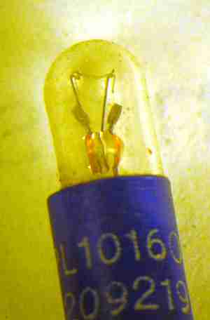 The current
pick is a bi–pin 14v 50 mA bulb because we happened to have a bunch of
them in stock, and the speeds and feeds are about right. Here's a picture
of one. The number is PL10160 if that helps anybody.
This bulb was used for the flashing lights in the mainframes Doug maintained
in the 70's, so there were a few laying around. It has 27 ohms cold
resistance. To modify this for gauge use, a hole is made in the top
on the belt sander. Just be gentle. The bulb is a vacuum one to
start with, so on breakthrough it will suck in air, dirt, and so
on. Most of this will shake back out if the filament survives. The bulb
is precisely .200 inch OD, so you can slip it into that size hole in
some plumbing and the base will not pass the hole. Then you can apply
your sealant of choice.
The current
pick is a bi–pin 14v 50 mA bulb because we happened to have a bunch of
them in stock, and the speeds and feeds are about right. Here's a picture
of one. The number is PL10160 if that helps anybody.
This bulb was used for the flashing lights in the mainframes Doug maintained
in the 70's, so there were a few laying around. It has 27 ohms cold
resistance. To modify this for gauge use, a hole is made in the top
on the belt sander. Just be gentle. The bulb is a vacuum one to
start with, so on breakthrough it will suck in air, dirt, and so
on. Most of this will shake back out if the filament survives. The bulb
is precisely .200 inch OD, so you can slip it into that size hole in
some plumbing and the base will not pass the hole. Then you can apply
your sealant of choice.
|
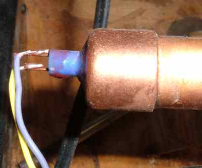 Here is the gauge plumbed into the real vacuum system. It is epoxied
into the pipe cap, which is in turn glued on with a 50:50 mixture
of beeswax and rosin. Both of those can be had at McMaster–Carr.
The red stuff is Glyptal lacquer, available at Caswell Plating. The above
compounds are really useful in medium vacuum work. The former melts for
easy removal, while the Glyptal polymerizes upon baking to be a very low
vapor pressure leak filler. Here we just used it to see if there was
a leak at all – if there was, the gauge tells you quick when
the leak is covered in Glyptal, and the usual procedure from there is
to really fix the leak with solder or something like that.
To make the beeswax and rosin mixture, you will initially
have to heat it above 100 C, using maybe an oil bath and melting equal
weights of the components in a little jar. I used a pyrex beaker and
an alcohol lamp here. Once it has been made, it
doesn't have to get as hot to remelt, it takes lots of heat that first time
just to get the rosin to dissolve in the wax. After that, you can use
boiling water to remelt it. I'm sure the ultra high vacuum guys are
squirming at this point, but the truth is, this stuff is a lot lower
vapor pressure than say, rust, cat hair, fingerprints, and all the other
stuff an amateur gets into a vacuum system. It's never been an issue here,
as we're not even trying to go to 10-9
mm of Hg or below. We just want to do metal vapor deposition and play
some games with protons.
Here is the gauge plumbed into the real vacuum system. It is epoxied
into the pipe cap, which is in turn glued on with a 50:50 mixture
of beeswax and rosin. Both of those can be had at McMaster–Carr.
The red stuff is Glyptal lacquer, available at Caswell Plating. The above
compounds are really useful in medium vacuum work. The former melts for
easy removal, while the Glyptal polymerizes upon baking to be a very low
vapor pressure leak filler. Here we just used it to see if there was
a leak at all – if there was, the gauge tells you quick when
the leak is covered in Glyptal, and the usual procedure from there is
to really fix the leak with solder or something like that.
To make the beeswax and rosin mixture, you will initially
have to heat it above 100 C, using maybe an oil bath and melting equal
weights of the components in a little jar. I used a pyrex beaker and
an alcohol lamp here. Once it has been made, it
doesn't have to get as hot to remelt, it takes lots of heat that first time
just to get the rosin to dissolve in the wax. After that, you can use
boiling water to remelt it. I'm sure the ultra high vacuum guys are
squirming at this point, but the truth is, this stuff is a lot lower
vapor pressure than say, rust, cat hair, fingerprints, and all the other
stuff an amateur gets into a vacuum system. It's never been an issue here,
as we're not even trying to go to 10-9
mm of Hg or below. We just want to do metal vapor deposition and play
some games with protons.
|
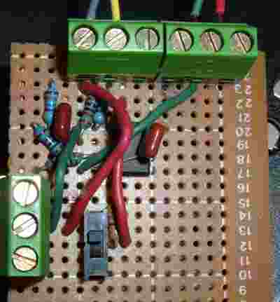 Here are the electronics. As you can see, this was whomped up in
no time on a piece of not very good perfboard. The opamp used was
a TLV 4112, which is a 5v high current opamp, so no output follower
for current boosting was needed. The switch was a mistake. At one
point the system was pumping down so low that Doug thought we needed
and could get more range by trying a higher value balancing resistor
and heating the element more to make things more sensitive. Well, at
any sort of incandescence, the tungsten filament dies very fast if there
is any air or water vapor present. They will be in most medium vacuum
systems. Note that 1% metal film resistors are used throughout. Not
sure if this matters, they just happened to be in stock, so why not?
There is a second section available in the opamp and on the terminal
strips, as the final vacuum system will need at least two of these.
We definitely have an urge to lay out a PCB for this design, once finalized
and sell the result to other amateurs. It just offends us that you'd
otherwise have to pay on the order of a grand for this sort of thing,
even used. Look how simple it is! OK, for the big bucks you get a nice
vacuum flange that you have to mate on your system at your cost...gee.
Here are the electronics. As you can see, this was whomped up in
no time on a piece of not very good perfboard. The opamp used was
a TLV 4112, which is a 5v high current opamp, so no output follower
for current boosting was needed. The switch was a mistake. At one
point the system was pumping down so low that Doug thought we needed
and could get more range by trying a higher value balancing resistor
and heating the element more to make things more sensitive. Well, at
any sort of incandescence, the tungsten filament dies very fast if there
is any air or water vapor present. They will be in most medium vacuum
systems. Note that 1% metal film resistors are used throughout. Not
sure if this matters, they just happened to be in stock, so why not?
There is a second section available in the opamp and on the terminal
strips, as the final vacuum system will need at least two of these.
We definitely have an urge to lay out a PCB for this design, once finalized
and sell the result to other amateurs. It just offends us that you'd
otherwise have to pay on the order of a grand for this sort of thing,
even used. Look how simple it is! OK, for the big bucks you get a nice
vacuum flange that you have to mate on your system at your cost...gee.
|
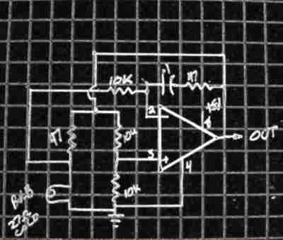 Here is the very simple schematic. We used the TLV-4112 as we had
them in stock, and they have plenty of current output available to
drive a small lamp such as this without help. Simple is good. You
should, of course, bypass the 5v power on board. We use a little supply
that puts out 5v and ±12v to support the vacuum system in
general. This is just a small switcher we bought and put into a
plastic box with binding posts. Total cost was under $20 compared
to the normal cost for a bench supply. It was fun processing this
image in the Gimp to make it readable. It sure is hard to take a good
picture of a pencil drawing on graph paper. Next time I will skip
the graph paper. Stuck with the pencil as that's what fits through
the stencils. Yeah, I should get a schematic capture program.
On the other hand, that whole production, including the drawing
took under 5 minutes. "Too fussy wastes manhours."
Here is the very simple schematic. We used the TLV-4112 as we had
them in stock, and they have plenty of current output available to
drive a small lamp such as this without help. Simple is good. You
should, of course, bypass the 5v power on board. We use a little supply
that puts out 5v and ±12v to support the vacuum system in
general. This is just a small switcher we bought and put into a
plastic box with binding posts. Total cost was under $20 compared
to the normal cost for a bench supply. It was fun processing this
image in the Gimp to make it readable. It sure is hard to take a good
picture of a pencil drawing on graph paper. Next time I will skip
the graph paper. Stuck with the pencil as that's what fits through
the stencils. Yeah, I should get a schematic capture program.
On the other hand, that whole production, including the drawing
took under 5 minutes. "Too fussy wastes manhours."
|
Any digital or analog meter can be used to read this gauge. You can
sort of calibrate it via looking at where the knees are on the curves
given for the thermocouple gauge in the link above, with a little mental
interpolation. This is a relative gauge at any rate. Ours reads a little
over 3.5v at atmospheric, and got down to about .55v at one point with
a tight door gasket on the system. The bulb is running at
1/2 of these voltages to reach a particular constant temperature of
a couple hundred °C where the tungsten filament has a resistance of 47 ohms.
As tungsten has a positive coefficient of resistance, the
bridge connections were reversed, and a 47 ohm balancing resistor was
used. The idea here is to force the tungsten element to about double its
resistance due to heating, but not heat it up too far. Tungsten and air
get along a bit too well at high temperatures. An improvement on this
design would include using fatter tungsten wire for the element. Experiments
are underway to find a good one that is gettable by everyone, and to find
out if maybe with the lower resistance a 4 wire connection to it will be
needed. We are also considering trying a model engine glow plug. These
are (were?) made with platinum wire as the element. It doesn't have
quite the thermal coefficient that tungsten does, but it doesn't take
much to make this circuit work with the full gain of the opamp available.
Stay tuned. We really want to make something here we can sell in bulk,
that is cheap and easy to apply. The glow plug, if it works, would have
some advantages, as it already has threads and is fairly airtight.
Update: I went to Central Hobbies and got one each of every type glow
plug they sell. I ran current/voltage curves on some of them, and found
out that they have enough temperature coefficient to work, but have
very low base resistance, and may consume too much power or make
too much heat. A real test is obviously in order. At this time, the
cheaper Fox plugs seem best for this. Based on the curves, I would set
these to run at about 0.7v and 1.7 amp at room temperature and atmosphere.
That's going to take a pretty hefty output stage to drive, and there
will likely be problems if the connections aren't really good, but it
still seems worth pursuing. For one thing, the filament is red at this
operating point, but will go all day without failure in STP conditions,
where a tungsten filament would last only a couple of seconds. The high
temperature operating point is good as then enviornmental temperature
affects the reading a lot less. Ten degrees is just a lot smaller
fraction of 900 than it is of 100, whether °C or °F. I have no
clue whether the action of hot platinum on residual gasses will be
a positive or negative thing. One thing for sure, the mount for the
glow plug will need a heat sink if it is going to be affixed to the
system with beeswax–rosin mixture.
Coulter's Smithing Home
Here's how to contact us:
Contact information