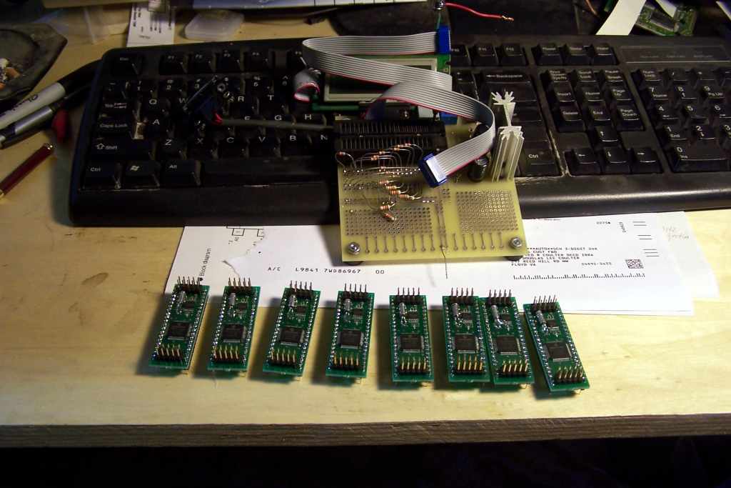
 Here are a few of the logger boards, with the version of the Mobo we use to test them
after building them -- this lashup finds all the bad solder joints and so on.
The stakes on the top of the logger board emit the two RS-232 ports on one end, and
some pins we use to drive an LCD display on the other end -- the PIC has more
than the 40 useful pins a DIP header will allow. Just add 5v, your code, and go!
PIC pins tend to be more useful than most micro-controllers. There are regular serial ports,
I2C and SPI, A/D inputs, PWM outputs, comparators that do both analog and interrupts to the CPU,
and most pins can be assigned to more than one function, depending on your needs.
As plain old I/O pins, they put out enough to burn up a normal LED, and as inputs
are CMOS high impedance. We've even used them to switch low level audio (to ground or not)
without having noise problems in good layouts, which this is.
Here are a few of the logger boards, with the version of the Mobo we use to test them
after building them -- this lashup finds all the bad solder joints and so on.
The stakes on the top of the logger board emit the two RS-232 ports on one end, and
some pins we use to drive an LCD display on the other end -- the PIC has more
than the 40 useful pins a DIP header will allow. Just add 5v, your code, and go!
PIC pins tend to be more useful than most micro-controllers. There are regular serial ports,
I2C and SPI, A/D inputs, PWM outputs, comparators that do both analog and interrupts to the CPU,
and most pins can be assigned to more than one function, depending on your needs.
As plain old I/O pins, they put out enough to burn up a normal LED, and as inputs
are CMOS high impedance. We've even used them to switch low level audio (to ground or not)
without having noise problems in good layouts, which this is.
The motivation for doing this, other than pure cheapness was, errrm, cheapness. Doug wanted to use these as data loggers in the Fusion setup, as they are inexpensive to replace should some errant EMP fry one. This has been a problem with the over billion watt pulses we sometimes play with, and a PC is plain old expensive and hasseliferous to replace. Even if we cook one of these, there's a better than even chance that the EEPROM I2C daughter-board still has the data on it, which could be read elsewhere.
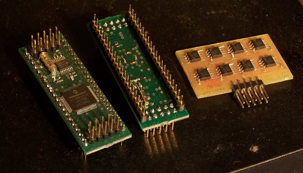 Here's a close up picture of both sides of the logger board, and the prototype eeprom board.
You can see the 32 khz xtal on the backside in this photo, and perhaps some of the bypass caps.
Boy, those 0402 smd parts aren't for the faint of heart! We put these down with a Metcal soldering station,
Kester 952 flux, and a stereo microscope...on a coffee-free day. At least the LED on the top was a
602 size. The Metcal soldering station makes this easier than you might think, though. They've really scienced out
things like tip shape for holding just the right amount of solder and no bridging, and perfect temperature
control. The big high density chips are done with a "horse hoof" tip in only a couple of seconds apiece,
they are actually the easiest part to do.
A very expensive tool that even a cheapskate can love once you use
it a little. Pays for itself right away. And yes, we've tried just about everything
else there is for this job, and there is simply no comparison whatever.
Here's a close up picture of both sides of the logger board, and the prototype eeprom board.
You can see the 32 khz xtal on the backside in this photo, and perhaps some of the bypass caps.
Boy, those 0402 smd parts aren't for the faint of heart! We put these down with a Metcal soldering station,
Kester 952 flux, and a stereo microscope...on a coffee-free day. At least the LED on the top was a
602 size. The Metcal soldering station makes this easier than you might think, though. They've really scienced out
things like tip shape for holding just the right amount of solder and no bridging, and perfect temperature
control. The big high density chips are done with a "horse hoof" tip in only a couple of seconds apiece,
they are actually the easiest part to do.
A very expensive tool that even a cheapskate can love once you use
it a little. Pays for itself right away. And yes, we've tried just about everything
else there is for this job, and there is simply no comparison whatever.
The eeprom board was made on our PCB line, which doesn't yet do plated through holes, so Dale put all the chips on one side, and only ran power and ground on the other, soldering through wires where power/ground vias would be. This could obviously be reduced in size later on when we make a layout for a real PCB house. This board gives 64kx8 of byte-writeable eeprom on the I2C bus. The idea is to have it pluggable, like a key-flash drive, so it can be used for much the same set of purposes, only less expensive. I used the same stakes as for the comm and LCD on the logger board, so as to have all using the same connectors, cheapness again.
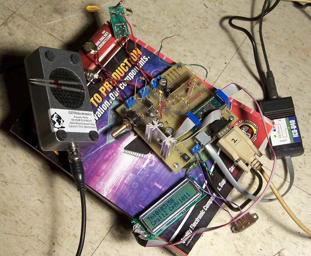 Here is an example project using this board. I obtained a very nice Geiger tube from
GEO on the Fusor Forum, and needed the rest of the stuff to make a useful counter.
I plan to put this in a box and make it portable. It is operating in this picture, counting
the alpha rays from a couple of thoriated tungsten welding rods for my TIG welder. HV for the
Geiger tube is created with a CCFL inverter from DigiKey, driven via PWM from the PIC using
an IRF 7105 as a power amplifier, and regulated using a resistive divider and an A/D input on
the PIC. The software is dirt-simple for all this, and I am using one of the RS-232 outputs to
stream debug information to HyperTerminal (ugh) on the PC. The LCD is driven directly off one
of the stake outputs from the logger board, back-light included as we put power pins on that connector
as well as the drive signals. The idea was to make it easy to snatch the logger out of the
mobo prototype and put it in a real project with minimal fuss. This is a very nice, sensitive
counter using a very thin window that passes even low energy alpha and X rays. It uses two
transistors, one as a preamp to drive the PIC (not really needed) and the other an LM395 to
direct-drive a small speaker so I can hear the clicks. This makes it easy to instantly notice
if the counts are random (natural radioactivity) or not (maybe something produced here that
might have 60 Hz hum on it). Got to set yourself up for those Fleming moments in science!
Yes, this is very "Hay-Wired" which is all it needs to be for a prototype. "Too fussy wastes man-hours"
(Robert Heinlein). This way it's easy to take apart to reuse it all as well.
Here is an example project using this board. I obtained a very nice Geiger tube from
GEO on the Fusor Forum, and needed the rest of the stuff to make a useful counter.
I plan to put this in a box and make it portable. It is operating in this picture, counting
the alpha rays from a couple of thoriated tungsten welding rods for my TIG welder. HV for the
Geiger tube is created with a CCFL inverter from DigiKey, driven via PWM from the PIC using
an IRF 7105 as a power amplifier, and regulated using a resistive divider and an A/D input on
the PIC. The software is dirt-simple for all this, and I am using one of the RS-232 outputs to
stream debug information to HyperTerminal (ugh) on the PC. The LCD is driven directly off one
of the stake outputs from the logger board, back-light included as we put power pins on that connector
as well as the drive signals. The idea was to make it easy to snatch the logger out of the
mobo prototype and put it in a real project with minimal fuss. This is a very nice, sensitive
counter using a very thin window that passes even low energy alpha and X rays. It uses two
transistors, one as a preamp to drive the PIC (not really needed) and the other an LM395 to
direct-drive a small speaker so I can hear the clicks. This makes it easy to instantly notice
if the counts are random (natural radioactivity) or not (maybe something produced here that
might have 60 Hz hum on it). Got to set yourself up for those Fleming moments in science!
Yes, this is very "Hay-Wired" which is all it needs to be for a prototype. "Too fussy wastes man-hours"
(Robert Heinlein). This way it's easy to take apart to reuse it all as well.
 Here's a screen shot of the CCS development environment as used here on this project. Sadly, their
nice IDE is a windows-only affair, so this is running on XP. They DO have a Linux compiler and driver
for their ICD, so we'll be lashing up something around that pretty soon. Probably not as feature
packed but it would avoid having to dual boot. Here you can see on the hyper-terminal screen that
I've turned the rotary encoder and pushed the button on it -- all nicely debounced.
Most browsers (this is only tested in Firefox/Ubuntu) should show the screen shot full size
if you right-click on it and ask for a display. Reducing it made the text unreadable here.
You can see why there are separate display outputs for CPS and CPM -- natural radiation is quite
random, so you really need some averaging. I am still figuring out what UI I want so I can
finish the code and stuff it in a box with some batteries. At a minimum it will be able
to store a few measurements in the on-chip eeprom for later upload to a PC. It's just a question
of things like "do we estimate the CPM from CPS (or CPH!) in real-time" or not, stuff like that.
For portable use, the LCD back-light will be on a push-button to conserve batteries, as this
is the major part of the current consumption! The CCFL used is 5v in to 700v out, which we
voltage-double and drive at about 3.5v average input to get the 850v DC for the Geiger tube.
The simple software regulation loop gives far better regulation than
this needs, on the order of 1 volt.
Here's a screen shot of the CCS development environment as used here on this project. Sadly, their
nice IDE is a windows-only affair, so this is running on XP. They DO have a Linux compiler and driver
for their ICD, so we'll be lashing up something around that pretty soon. Probably not as feature
packed but it would avoid having to dual boot. Here you can see on the hyper-terminal screen that
I've turned the rotary encoder and pushed the button on it -- all nicely debounced.
Most browsers (this is only tested in Firefox/Ubuntu) should show the screen shot full size
if you right-click on it and ask for a display. Reducing it made the text unreadable here.
You can see why there are separate display outputs for CPS and CPM -- natural radiation is quite
random, so you really need some averaging. I am still figuring out what UI I want so I can
finish the code and stuff it in a box with some batteries. At a minimum it will be able
to store a few measurements in the on-chip eeprom for later upload to a PC. It's just a question
of things like "do we estimate the CPM from CPS (or CPH!) in real-time" or not, stuff like that.
For portable use, the LCD back-light will be on a push-button to conserve batteries, as this
is the major part of the current consumption! The CCFL used is 5v in to 700v out, which we
voltage-double and drive at about 3.5v average input to get the 850v DC for the Geiger tube.
The simple software regulation loop gives far better regulation than
this needs, on the order of 1 volt.